Welcome to ROSMASTER M1 PRO repository
1.Robotic Arm Basic Usage
Robotic Arm Basic Usage
Robotic Arm Basic Usage1. Course Content2. Preparation3.Basic Knowledge Definitions4. Case Demonstration4.1 Robotic Arm Joint Control and Torque Control4.2 End-effector Pose Control4.3 Real-time End-effector Pose Display5. Robotic Arm Middle Position Calibration6. Grasping Offset Calculation Standard7. Notes for DIY Robotic Arm Grasping
1. Course Content
This section is the introductory course for robotic arm related functions. It mainly leads users to understand the definitions of robotic arm related coordinate frames, master the basic control methods and debugging techniques of the robotic arm, and lay the foundation for subsequent cases such as robotic arm grasping, sorting, and tracking. The course content includes:
Basic Knowledge Definitions: introduces the definitions of the ROS robot coordinate frame, the robotic arm end-effector TCP coordinate frame, the robotic arm reference base coordinate frame (measure), and the camera optical axis coordinate frame, as well as how to determine them using the right-hand rule.
Robotic Arm Basic Control: demonstrates robotic arm joint angle control, torque enabling/disabling, and spatial position control based on the end-effector pose (x, y, z, roll, pitch, yaw, gripper), and explains how to add end-effector offsets via offset_x, offset_y, offset_z.
Real-time End-effector Pose Display: views the robotic arm joint angles and end-effector pose in real time through a visualization tool, and supports toggling the torque on/off with the spacebar to achieve drag teaching.
Robotic Arm Middle Position Calibration: explains how to perform middle position calibration when the robotic arm is bent or the servo angles are offset.
Grasping Offset Calculation Standard: introduces the adjustment principles and steps for the X/Y/Z axis offsets and the grasping angle, to compensate for systematic errors such as camera measurement errors and servo backlash.
Notes for DIY Robotic Arm Grasping: provides a correspondence table between gripper angles and object sizes, to avoid servo stall and burnout caused by unreasonable angle settings.
Important
When the robotic arm grasps objects, the gripper angle must be controlled reasonably. Never set it too large or too small, otherwise servo No. 6 may stall and burn out.
The poses and offsets involved in this section are all based on the measure reference base coordinate frame. Before learning, it is recommended to first master the method of determining the right-handed coordinate frame.
2. Preparation
ros2 launch yahboomcar_bringup car_base.launch.py odom_tf_source:=ekf
3.Basic Knowledge Definitions
ROS robot coordinate frame definition
The ROS robot coordinate frame follows the right-hand rule, taking the robot body as the reference:
X axis (red): points to the robot's front
Y axis (green): points to the robot's left
Z axis (blue): points to the robot's top (perpendicular to the ground, upward)
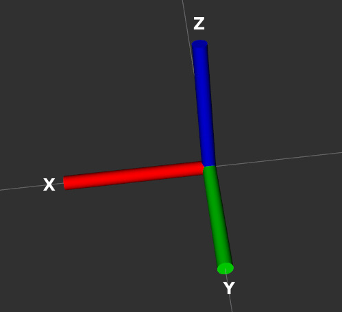
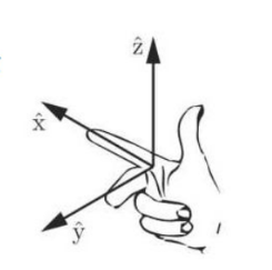
Method for determining the right-hand rule: point the right thumb in the positive X axis direction, the index finger in the positive Y axis direction, and the direction in which the middle finger naturally bends is the positive Z axis direction.
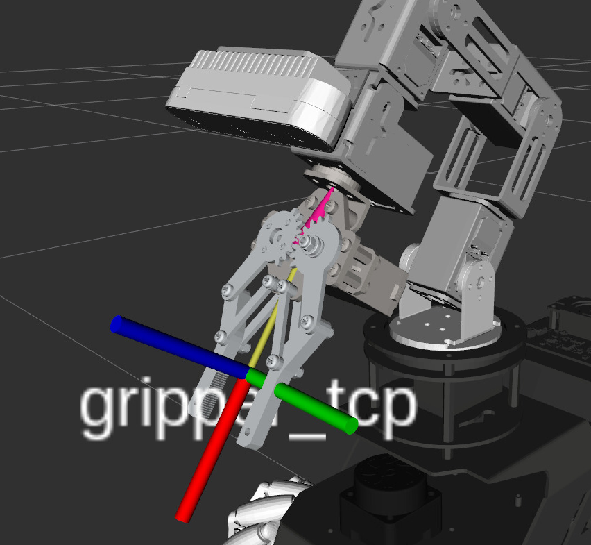
Robotic arm end-effector TCP coordinate frame
TCP (Tool Center Point) is the working center point of the robotic arm end-effector (gripper), used to represent the position and pose of the robotic arm end-effector in 3D space. In kinematics calculations, the TCP is the reference point for forward and inverse kinematics solutions; all end-effector poses are expressed as the position and orientation of the TCP relative to the base coordinate frame, and this coordinate frame is defined in the robot's URDF model.
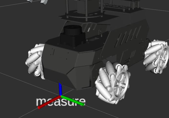
Robotic arm reference base coordinate frame (measure)
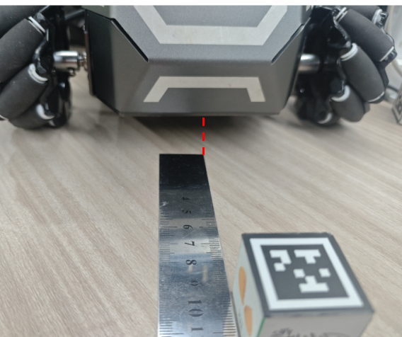
The measure coordinate frame is the robotic arm's reference base coordinate frame, whose origin is located at the vertical projection point onto the ground of the center point of the car's front. This coordinate frame is the reference frame for the robotic arm's kinematics calculations; all robotic arm end-effector positions and target point coordinates are expressed relative to the measure coordinate frame. In the ROS TF transform tree, the measure coordinate frame serves as the parent coordinate frame of the robotic arm related coordinate frames.
Tip
The reason for choosing this point as the robotic arm motion reference coordinate frame is that it facilitates observing and measuring the robotic arm end-effector position and the actual position of objects
Camera optical axis coordinate frame
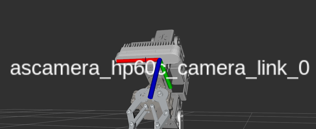
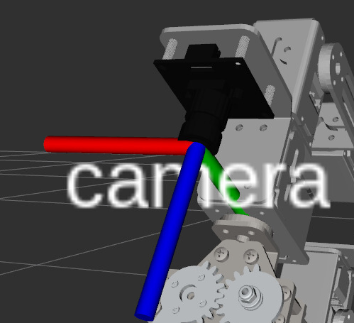
The camera optical axis coordinate frame takes the camera optical center (optical center) as the origin, with the Z axis along the camera optical axis pointing to the front of the camera (i.e., the shooting direction), the X axis pointing to the right of the image, and the Y axis pointing to the bottom of the image. This coordinate frame is used to project the position of objects in 3D space onto the 2D image plane, and is the basic coordinate frame for algorithms such as visual distance measurement and target localization.
Depth camera
USB monocular camera
4. Case Demonstration
4.1 Robotic Arm Joint Control and Torque Control
Refer to the prerequisite tutorial 【Chassis Control — ROS Control】
4.2 End-effector Pose Control
Example: end-effector to: front 0.15m / left 0.05m / height 0.10m, pitch 60° (downward pose), gripper 30° (the larger the gripper value, the smaller the opening)
xxxxxxxxxxros2 service call /move_to_pose interfaces/srv/MoveToPose "{x: 0.15, y: 0.05, z: 0.10, roll: 0.0, pitch: 60.0, yaw: 0.0, gripper:30}"
Example: end-effector to: front 0.15m / left 0.05m / height 0.10m, pitch 0° (horizontal pose), roll 60.0 (gripper rotation), gripper 110°
xxxxxxxxxxros2 service call /move_to_pose interfaces/srv/MoveToPose "{x: 0.15, y: -0.07, z: 0.15, roll: 60.0, pitch: 0.0, yaw: 0.0, gripper: 110}"
The above examples control the end-effector to move to the theoretically calculated position of the robotic arm kinematics. However, in subsequent robotic arm grasping cases, it is often necessary to add an offset to the end-effector movement so that the gripper grasps different positions to achieve a better grasping effect. You can add the end-effector position offsets via offset_x, offset_y, offset_z. For example: based on the previous step, offset the end-effector by 0.02 meters along the x axis, 0.01 meters along the y axis, and 0.03 meters along the z axis
xxxxxxxxxxros2 service call /move_to_pose interfaces/srv/MoveToPose "{x: 0.15, y: -0.07, z: 0.15, roll: 60.0, pitch: 0.0, yaw: 0.0, offset_x: 0.02, offset_y: 0.01, offset_z: 0.03, gripper: 110}"
If the specified end-effector pose is kinematically unreachable, the program will give an approximate solution near the target point and indicate the error relative to the target value

Restore the robotic arm to its initial pose
xxxxxxxxxxros2 service call /reset_arm_pose std_srvs/srv/Trigger
4.3 Real-time End-effector Pose Display
xxxxxxxxxxros2 run common_demo arm_visualization
arm1-arm6 are the corresponding angles of the robotic arm joints, and End-Effector Pose is the robotic arm end-effector pose
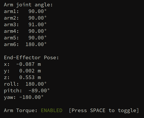
Press the spacebar to enable/disable the robotic arm torque; when the robotic arm torque is disabled, you can slowly drag the robotic arm to move

Press the spacebar again to enable the torque and fix the robotic arm's pose

5. Robotic Arm Middle Position Calibration
Move the robotic arm to the middle position
xxxxxxxxxxros2 service call /set_arm_joints interfaces/srv/ArmPosition "{request_joints: [90, 90, 90, 90, 90, 180]}"
Check whether the robotic arm is straight. If the robotic arm is bent or a servo angle is obviously offset, follow the steps below to calibrate
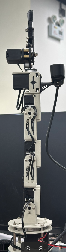
Disable the robotic arm torque
xxxxxxxxxxros2 service call /set_arm_torque std_srvs/srv/SetBool "{data: false}"
Manually straighten the robotic arm, making it form a straight line as much as possible, with the gripper fully closed, and then request the calibration service
xxxxxxxxxxros2 service call /calibrate_arm_offset std_srvs/srv/Trigger
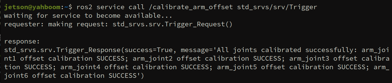
6. Grasping Offset Calculation Standard
When subsequent courses involve robotic arm grasping with systematic errors or the need to adjust the grasping point position, refer to the following offset calculation method to adjust and compensate the end-effector position
Important
Systematic errors mainly come from camera measurement errors, the different servo joint backlash of each robotic arm, and link rigidity degradation
Adjustment Principles:
X-axis offset (front-back direction)
Positive value: the grasping point moves forward (away from the robot body); negative value: the grasping point moves backward (toward the robot body)
Y-axis offset (left-right direction)
Positive value: the grasping point moves left (the left side of the robot's forward direction); negative value: the grasping point moves right (the right side of the robot's forward direction)
Z-axis offset (up-down direction)
Positive value: the grasping point moves up; negative value: the grasping point moves down
Adjustment scenario: used when grasping is too high or too low, often to compensate for the height difference between the gripper and the object surface
Grasping angle (gripper rotation angle)
Unit: degrees
Adjustment scenario: adjusted when the object needs to be grasped from a specific angle; adjustment is not recommended
Adjustment Steps:
Perform a grasping operation once, and record the deviation direction between the actual grasping position and the ideal position
According to the right-handed coordinate frame principle, determine the direction and sign that need to be adjusted
Example 1: the grasping point is too far back
You need to increase the offset in the x-axis direction (increase a positive value); conversely, if the grasping point is too far forward, you need to subtract the offset (increase a negative value)
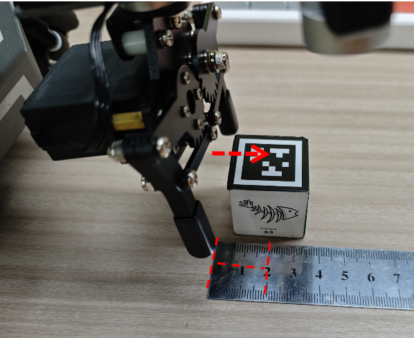
Example 2: the grasping point is too far left
You need to decrease the offset in the y-axis direction (increase a negative value); conversely, if it is too far right, you need to increase the offset in the y-axis direction (increase a positive value)
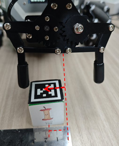
Example 3: the grasping point is too low
You need to increase the offset in the z-axis direction (increase a positive value); conversely, if it is too high, you need to decrease the offset (increase a negative value)
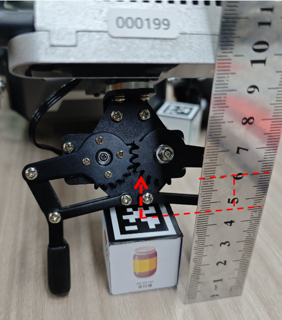
7. Notes for DIY Robotic Arm Grasping
Note: When the robotic arm grasps objects, the gripper angle needs to be controlled. An unreasonable angle setting may cause the servo to stall and burn out.
Here, a gripper angle correspondence table is compiled, recording approximately what servo angle needs to be set for grasping an object of every 0.5 cm size. You can reasonably adjust the angle set for your own grasping according to this table to avoid servo stall.
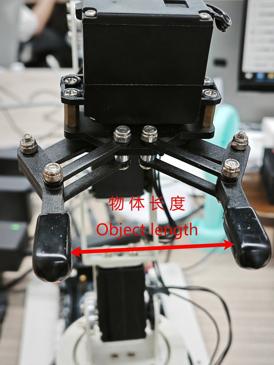
| Object length (unit: cm) | Servo angle (unit: degrees) |
|---|---|
| 0 | 180 |
| 0.5 | 176 |
| 1.0 | 168 |
| 1.5 | 160 |
| 2.0 | 152 |
| 2.5 | 143 |
| 3.0 | 134 |
| 3.5 | 125 |
| 4.0 | 115 |
| 4.5 | 105 |
| 5.0 | 95 |
| 5.5 | 80 |
| 6.0 | 57 |
| 6.0-6.4 | 0-57 |
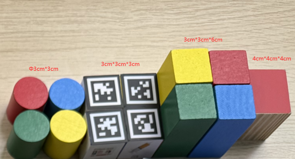
For example, the block we provide is 3cm in length, width, and height, so setting the servo angle to 134° can grasp it. Never set the angle too large or too small.
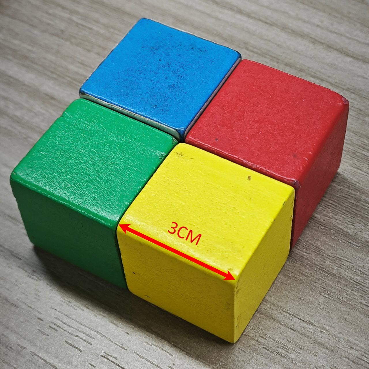
Note: This product provides four wooden blocks of different sizes and shapes. Grasping must be done strictly according to the block sizes marked in the tutorial. If the program is set to grasp a 3cm block but a 4cm block is actually placed for grasping, it will cause servo No. 6 to be damaged.