Welcome to ROSMASTER M1 PRO repository
7.Color Block Sorting
Color Block Color Sorting
Color Block Color Sorting1. Course Content2. Preparation3. Case Demonstration4. Color Block Color Calibration5. Core Source Code AnalysisDepth Camera Mode _pixel_to_measureMonocular Camera Mode _block_pnp_to_measure
1. Course Content
This feature implements the program acquiring images through the camera and, according to the key input, selecting the color of the color block to be sorted. The program will recognize the color blocks that meet the requirements, grasp them, and finally place them in a set position.
Important
The grasping point calculation methods differ between the depth camera and the USB monocular camera: the depth camera obtains the spatial coordinates of the target center point through the depth map, while the monocular camera performs PnP solving to obtain the spatial position of the target center point using a known side length (0.03m)
The wooden block used in this section: 30x30x30mm color block
2. Preparation
ros2 launch yahboomcar_bringup arm_demo.launch.py demo:=color_sort_lab
3. Case Demonstration
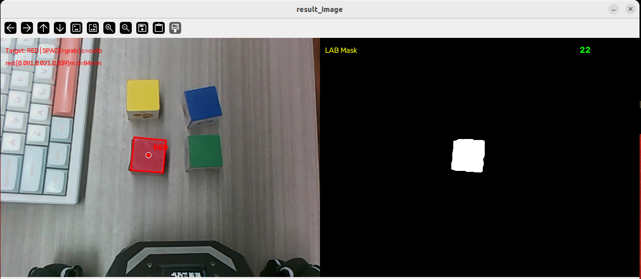
Place the 30x30x30mm color block provided with the product below the camera. After the color block appears in the image, select the color block color using the following keys:
Key R: detect and sort the red block
Key G: detect and sort the green block
Key B: detect and sort the blue block
Key Y: detect and sort the yellow block
After pressing the spacebar, the chassis will first align with the target. After the chassis alignment with the target is complete, grasping is performed. After grasping is complete, the block is placed in different positions according to the color block's color. The robotic arm then resets, and pressing the spacebar again allows the next sorting round.
4. Color Block Color Calibration
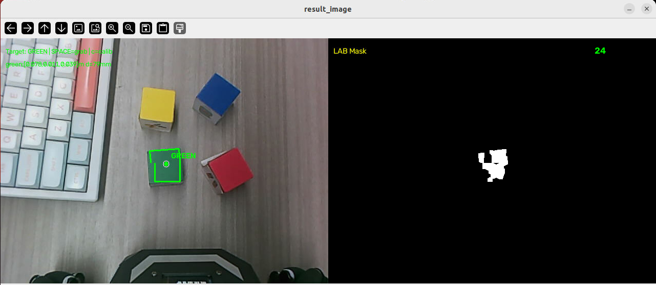
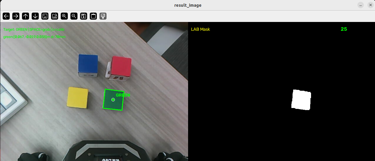
Due to lighting reasons, the preset LAB values in the program may not accurately distinguish the color blocks. In this case, the detected color can be calibrated. Here, calibrating the green block is taken as an example
Press G to select detection of the green block
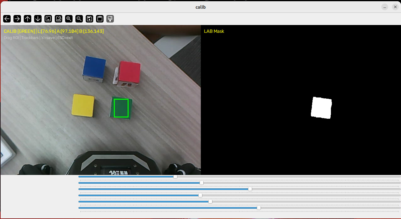
Press C to perform color calibration
Use the left mouse button to drag and draw a rectangular box on the color block to be recognized, then release the mouse and check whether the binarized image can accurately recognize the target color. The slider below can fine-tune the LAB values
Press the S key to save the calibration values to the parameter file, and press ESC to exit calibration
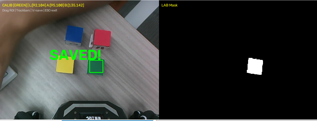
After that, the normal color sorting flow can be carried out
5. Core Source Code Analysis
Program path:
xxxxxxxxxx~/yahboomcar_ros2_ws/yahboomcar_ws/src/common_demo/common_demo/arm_demo/color_sort_lab.py
Depth Camera Mode _pixel_to_measure
Use "detection box center pixel + corresponding depth value" for pinhole back-projection:
Get depth:
depth_z = depth_image[py, px] / 1000.0(mm→m);≤0.01mis regarded as invalid and returnsNoneBack-project to the camera optical frame (using the intrinsic parameters fx, fy, cx, cy):
TF2 transform: construct a
PointStamped(frame is the depth image'sframe_id), and usetf_buffer.transform(..., 'measure')to transform to themeasureframe; retry 5 times on failureOffset correction: add the
depth_measureparameter →[mx, my, mz]
Monocular Camera Mode _block_pnp_to_measure
Prerequisite: the target is a square block with a known side length square_size; use cv2.solvePnP to solve the pose:
Tolerance 1: the minimum enclosing rectangle must be approximately square (aspect ratio ≤1.5), otherwise it is discarded
Corner pairing: sort the 4 corners of
minAreaRectin the order top-left→top-right→bottom-right→bottom-left (using coordinate sum/difference extrema), matching one-to-one with the square 3D corners centered at the origin with side lengthsquare_sizeon the Z=0 planesolvePnP: solve for the camera-frame pose
rvec/tvec;tvecis the coordinates of the block center in the camera frameTolerance 2: discard if the reprojection error >5px
Tolerance 3: the camera-frame depth
cam_zmust be within 0.02∼0.8 m (the robotic arm's working range)TF2 transform + add the
usb_camera_measureoffset correction →[mx, my, mz]
x def _pixel_to_measure(self, pixel_x, pixel_y, depth_image, camera_frame_id): if self.camera_K is None: return None
h, w = depth_image.shape px, py = int(round(pixel_x)), int(round(pixel_y))
if px < 0 or px >= w or py < 0 or py >= h: return None
# Depth value: mm -> m depth_z = depth_image[py, px] / 1000.0 if depth_z <= 0.01: return None
# Pixel coordinates -> camera optical coordinates fx = self.camera_K[0, 0] fy = self.camera_K[1, 1] cx = self.camera_K[0, 2] cy = self.camera_K[1, 2]
cam_x = (pixel_x - cx) * depth_z / fx cam_y = (pixel_y - cy) * depth_z / fy cam_z = depth_z
# Build the point in the camera frame point_cam = PointStamped() point_cam.header.stamp = rclpy.time.Time(seconds=0).to_msg() point_cam.header.frame_id = camera_frame_id point_cam.point.x = float(cam_x) point_cam.point.y = float(cam_y) point_cam.point.z = float(cam_z)
# TF2 transform to the measure frame try: for attempt in range(5): try: point_measure = self.tf_buffer.transform( point_cam, 'measure', timeout=Duration(seconds=1.0) ) # Apply the depth_measure offset mx = point_measure.point.x + self.depth_measure[0] my = point_measure.point.y + self.depth_measure[1] mz = point_measure.point.z + self.depth_measure[2] return [mx, my, mz] except Exception: if attempt < 4: time.sleep(0.05) continue raise except Exception as e: self.get_logger().warn(f"TF to 'measure' failed: {e}") return None
def _block_pnp_to_measure(self, block, camera_frame_id): """Monocular-mode pose estimation: the block is a fixed square (side length square_size); uses the 4 corners of the minimum enclosing rectangle as image points, solvePnP solves the camera-frame pose, then it is transformed to the measure frame """ if self.camera_K is None: return None
# Tolerance check 1: the bounding rectangle should be nearly square; filter out non-block contours _, (w, h), _ = block['rect'] if w <= 1.0 or h <= 1.0: return None aspect = max(w, h) / min(w, h) if aspect > 1.5: return None
# Sort the 4 corners: top-left -> top-right -> bottom-right -> bottom-left, matching the 3D object points one-to-one box = cv2.boxPoints(block['rect']).astype(np.float64) s = box.sum(axis=1) d = np.diff(box, axis=1).flatten() img_points = np.array([ box[np.argmin(s)], # top-left box[np.argmin(d)], # top-right box[np.argmax(s)], # bottom-right box[np.argmax(d)], # bottom-left ], dtype=np.float64)
# Square 3D corners (Z=0 plane, origin at the block center) half = self.square_size / 2.0 obj_points = np.array([ [-half, -half, 0.0], [ half, -half, 0.0], [ half, half, 0.0], [-half, half, 0.0], ], dtype=np.float64)
success, rvec, tvec = cv2.solvePnP( obj_points, img_points, self.camera_K, None ) if not success: return None
# Tolerance check 2: an excessive reprojection error means the corners do not match the square assumption reproj, _ = cv2.projectPoints( obj_points, rvec, tvec, self.camera_K, None ) reproj_err = float(np.mean(np.linalg.norm( reproj.reshape(-1, 2) - img_points, axis=1 ))) if reproj_err > 5.0: return None
cam_x, cam_y, cam_z = tvec[0][0], tvec[1][0], tvec[2][0] # Tolerance check 3: the depth should be within the arm's working range if cam_z < 0.02 or cam_z > 0.8: return None
point_cam = PointStamped() point_cam.header.stamp = rclpy.time.Time(seconds=0).to_msg() point_cam.header.frame_id = camera_frame_id point_cam.point.x = float(cam_x) point_cam.point.y = float(cam_y) point_cam.point.z = float(cam_z)
try: for attempt in range(5): try: point_measure = self.tf_buffer.transform( point_cam, 'measure', timeout=Duration(seconds=1.0) ) # Apply the usb_camera_measure offset to compensate for measurement error mx = point_measure.point.x + self.usb_camera_measure[0] my = point_measure.point.y + self.usb_camera_measure[1] mz = point_measure.point.z + self.usb_camera_measure[2] return [mx, my, mz] except Exception: if attempt < 4: time.sleep(0.05) continue raise except Exception as e: self.get_logger().warn(f"TF to 'measure' failed: {e}") return None