Welcome to ROSMASTER A1 PRO repository
6.Depth Camera Calibration
🎯 Depth Camera Calibration, Robotic Arm Center and Hand-Eye Spatial Offset Calibration (Depth Camera Hand-Eye Calibration)
1. Course Introduction and Calibration System
Before using Angstrong Nuwa-HP60C 3D Depth Camera for advanced embodied intelligent tasks such as robotic arm 3D spatial grasping, color block sorting, and machine code tracking, you must sequentially complete two major dimensional space calibrations:
Stage 1: Robotic Arm Bottom Servo Physical Center Calibration (
calibrate_arm_offset.py):The servo metal output shaft spline has discrete tooth pitch (each tooth pitch about 10° ~ 15°), after assembly and tightening screws, there is tiny mechanical tolerance between the physical mechanical zero position and algorithm theoretical zero position;
You must first calibrate the robotic arm each joint's physical zero position (joints 1~5 at 90° vertical straight, joint 6 gripper at 180° completely closed), establishing precise physical baseline for forward/inverse kinematics (FK/IK).
Stage 2: Depth Camera Hand-Eye Grasping Spatial Offset Calibration (
arm_offset):Nuwa-HP60C depth camera is fixed above the small arm side of the robotic arm (Eye-in-Hand). Due to installation processing tolerance, machine vibration, and tiny offset in gripper assembly zero position, there is a fixed physical offset in 3D space between the camera field of view center point and gripper closing center;
Run
arm_offsetnode, through hand-eye calibration homogeneous transformation matrix and robotic arm forward kinematics, calculate the 3D geometric deviation compensation (X_offset, Y_offset, Z_offset) between camera detection center and gripper center, eliminating hand-eye space error.
2. Calibration Stage 1: Robotic Arm Bottom Servo Physical Center Calibration (Hardware Physical Baseline)
Important
The depth camera hand-eye calibration node will call the robotic arm forward kinematics service to get the end matrix (get_end_point_mat) when calculating spatial world coordinates. If there is angle center deviation in the bottom servo, the calculated camera installation pose will inevitably have tilt drift, causing point cloud and gripper grasping point to not overlap! Therefore, robotic arm center calibration is the prerequisite and precondition step for hand-eye calibration.
2.1 Start Robotic Arm Center Calibration Program
Program supports modern dark GUI graphical and pure SSH terminal interactive command-line two modes:
x# Method A: Desktop / VNC environment graphical startup (Recommended)python3 ~/Rosmaster/rosmaster/calibrate_arm_offset.py
# Method B: Pure SSH terminal desktop-free startuppython3 ~/Rosmaster/rosmaster/calibrate_arm_offset.py --cli
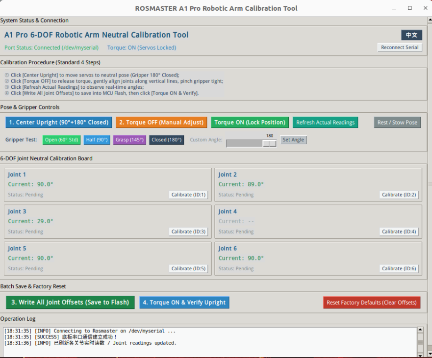
2.2 Core Calibration Four-Step Operation
Let robotic arm return to neutral straight position: Click 【1. Center Upright (90°+180° Closed)】 (CLI press
1), single-chip microcomputer sends initial theoretical angle[90, 90, 90, 90, 90, 180](gripper at 180° closed position);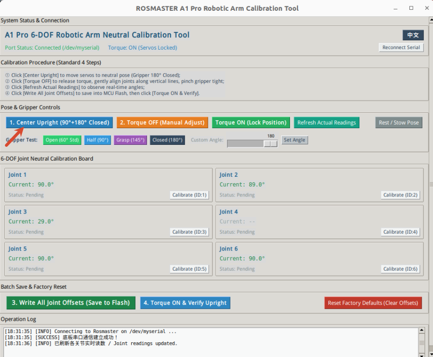
Turn off servo torque: Click 【2. Torque OFF (Manual Adjust)】 (CLI press
2), each joint motor releases force, gently adjust each joint by hand to strictly align with the mechanical vertical line, close joint 6 gripper to 180° aligned;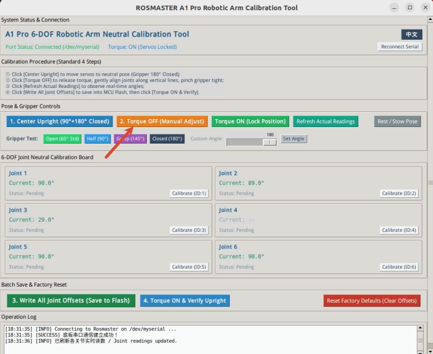
Write deviation save Flash: Click 【3. Write All Joint Offsets (Save to Flash)】 (CLI press
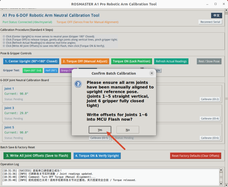
4), the chassis reads the current actual encoder readings of each servo, calculates the Offset and permanently stores it in the single-chip microcomputer Flash (not lost after power off);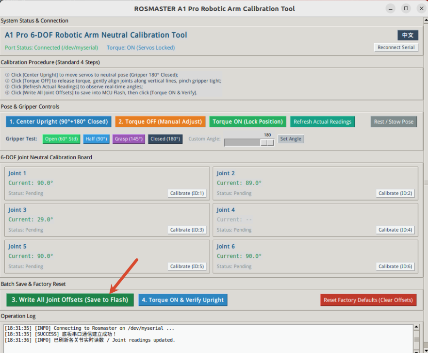
Click YES to confirm
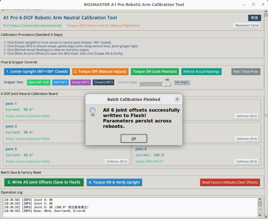
Success will show
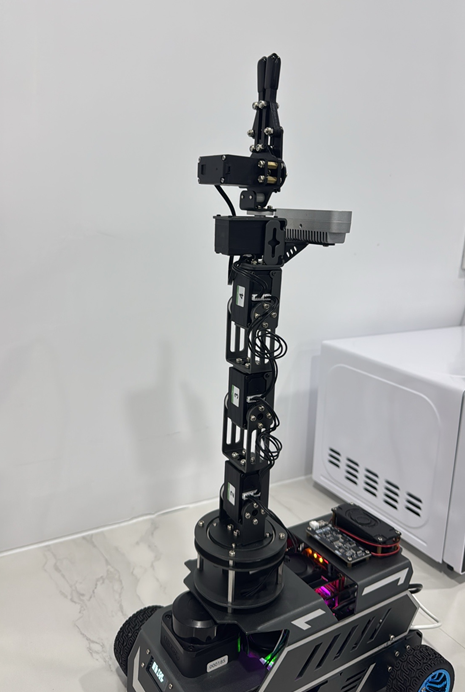
Turn on torque verification: Click 【4. Torque ON & Verify Upright】 (CLI press
7), power on and lock, verify if the robotic arm is as straight as a benchmark and the gripper is completely closed.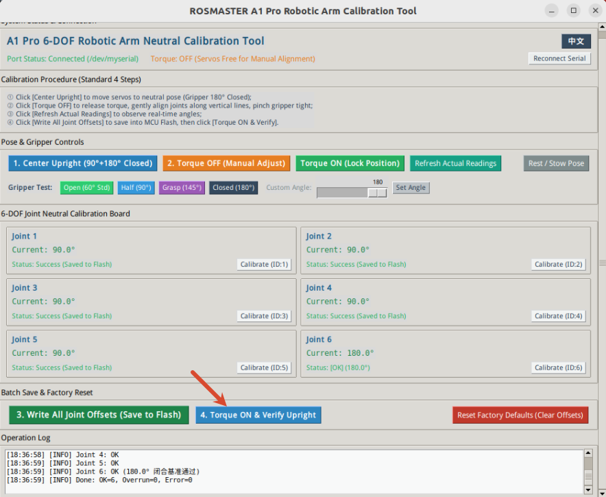
3. Calibration Stage 2: Depth Camera Hand-Eye Grasping Offset Calibration
After completing robotic arm center calibration, each joint has high-precision geometric angle baseline. Next, run depth camera hand-eye offset calibration to calculate the spatial relative coordinates between camera center and gripper.
3.1 Prepare Test Material and Environment
Prepare the matching 4×4 cm AprilTag machine code wooden block;
Ensure the car is placed stably, desktop lighting is even without strong light reflection.
3.2 Start Camera Driver and Inverse Solution Node
Start depth camera, robotic arm bottom driver and forward/inverse kinematics solution environment in Terminal 1:
xxxxxxxxxxros2 launch dofbot_pro_driver A1pro_camera_arm.launch.py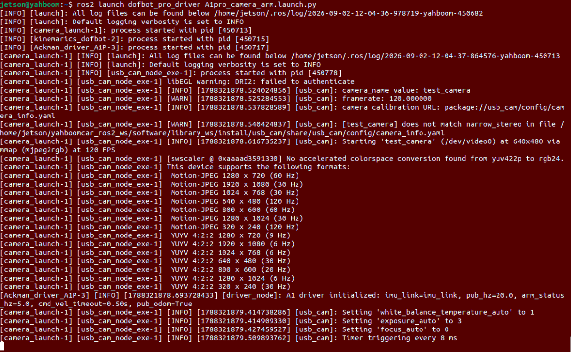
3.3 Start Hand-Eye Offset Calibration Program
Run depth camera exclusive offset calibration program in Terminal 2:
xxxxxxxxxxros2 run dofbot_pro_calibration arm_offset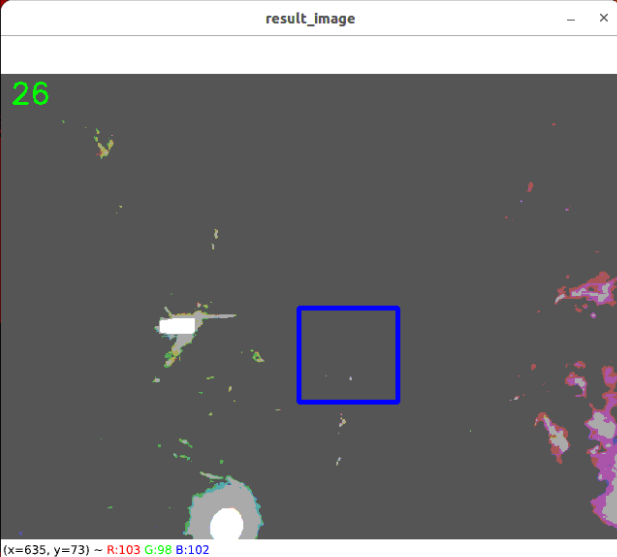
3.4 Practical Calibration Steps
Observe calibration guide frame: After program starts, the robotic arm will automatically move to the visual calibration observation pose; a calibration rectangle will appear in the center of the screen;
Place and align calibration material: Place the 4×4 cm AprilTag machine code wooden block on the desktop in front of the robotic arm, slightly adjust the block position so that it is exactly at the center of the rectangle in the image;
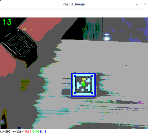
Confirm stable recognition:
A green center crosshair circle, four corner color circles, and detected ID label will be drawn in the image;
Terminal will print in real-time the physical depth value
cz(unit: meters) and spatial position coordinatespose_Tread from the tag center;
Press space to save parameters: Keep the image window in an active focus state, press keyboard **
Space key (SPACE)**;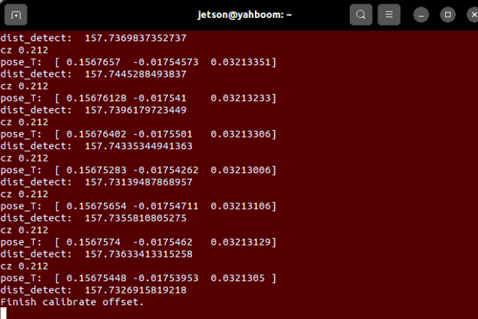
Terminal will output success prompt, the 3D compensation calculated by the program will be persistently written to the configuration file.
4. Offset Configuration File Description
The 3D spatial physical compensation calculated by the calibration program will be automatically written to the following configuration file:
xxxxxxxxxxdofbot_pro_ws/src/dofbot_pro_driver/config/offset_value.yaml
xxxxxxxxxxx_offset0.009368814795573138y_offset0.007718452024610358z_offset0.0x_offset: Camera and gripper front-rear direction millimeter installation deviation compensation;y_offset: Camera and gripper left-right direction millimeter installation deviation compensation;z_offset: Height compensation (usually keep 0.0, based on measured point cloud plane as standard).
If there is still extremely slight deviation to the left or front when actually grasping specific objects in the future, you can also directly edit this YAML configuration file to fine-tune.
5. Core Source Code Deep Analysis (arm_offset.py)
Source location: dofbot_pro_ws/src/dofbot_pro_calibration/dofbot_pro_calibration/arm_offset.py
1. Camera to Robotic Arm End External Parameter Matrix (EndToCamMat)
xxxxxxxxxx# Eye-in-Hand Camera Installation Pose External Parameter Transformation Matrixself.EndToCamMat = np.array([ [ 0, 0, 1, -0.101], [-1, 0, -0.028, 0.002], [ 0, -1, 0, 0.048], [ 0, 0, 0, 1.0 ]])2. Spatial Coordinate Solution and Forward Transformation
xxxxxxxxxxdef compute_heigh_from_location(self, camera_location): # 1. Convert camera coordinate system position to robotic arm end coordinate system PoseEndMat = np.matmul(self.EndToCamMat, self.xyz_euler_to_mat(camera_location, (0, 0, 0))) # 2. Robotic arm forward kinematics (FK) to get end pose homogeneous matrix in base EndPointMat = self.get_end_point_mat() # 3. Get material absolute 3D coordinates in world coordinate system WorldPose = np.matmul(EndPointMat, PoseEndMat) pose_T, pose_R = self.mat_to_xyz_euler(WorldPose) return pose_T3. Spatial Geometric Deviation Compensation Calculation
Through differential comparison with factory calibrated physical geometry origin ($XX = 0.145m, Y = -0.013m$), derive the final compensation value and write to file:
xxxxxxxxxxx_offset_value = 0.145 - pose[0]y_offset_value = -0.013 - pose[1]
offset_config['x_offset'] = float(x_offset_value)offset_config['y_offset'] = float(y_offset_value)with open(offset_file, 'w') as file:    yaml.dump(offset_config, file, default_flow_style=False)
6. Common Problem Troubleshooting
Q1: Report error "Cannot connect to Rosmaster (/dev/myserial)" when starting?
Solution: Execute
pkill -f "rosmaster/joy.py"to kill the process occupying the serial port from the joystick auto-start program, then start again.
Q2: No red alignment frame in image or machine code not detected?
Solution:
Ensure you are using the matching 4×4 cm AprilTag machine code wooden block (not 2×2cm);
Observe if the camera is overexposed, appropriately adjust ambient lighting, avoid desk lamp direct reflection;
Check if the camera's USB 3.0 data cable is inserted into the car's blue high-speed USB port.