Welcome to ROSMASTER A1 PRO repository
6.Color Block Sorting
🎨 Multi-Color Block Recognition and Sorting (Color Sorting)
1. Course Overview
The function implemented in this lesson can be simply understood as: camera distinguishes colors, grasps wooden blocks by color, automatically places them in corresponding grid cells.
The program uses HSV color space for image threshold filtering to recognize blocks of different colors such as red, green, blue, yellow, etc., calculates their 3D spatial coordinates, and after the robotic arm IK descent grasping, automatically rotates to the corresponding sorting bin to unload based on color type.
Note
The tutorial recommends using the accompanying 3×3 cm colored wooden blocks.
2. Preparation and Running
This case requires opening 3 terminals to start the system sequentially:
2.1 Start Camera Driver and Kinematics Solver Environment
Run in Terminal 1:
xxxxxxxxxxros2 launch dofbot_pro_driver A1pro_camera_arm.launch.py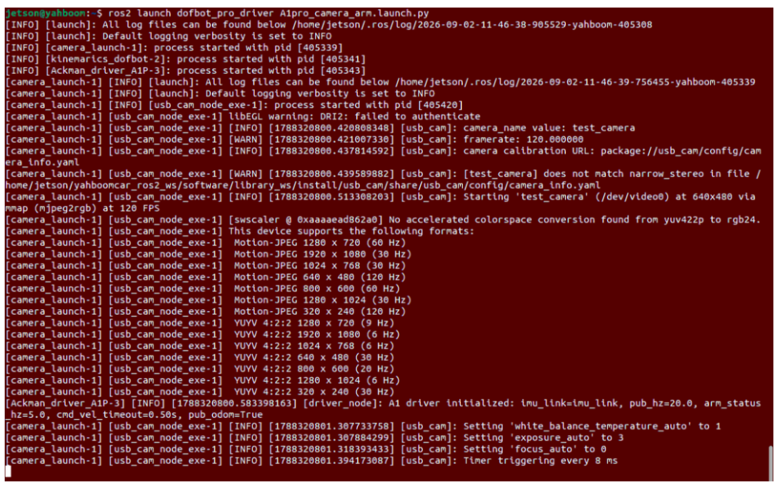
2.2 Start Robotic Arm Desktop Grasping Action Execution Node
Run in Terminal 2:
xxxxxxxxxx# Depth camera version (Nuwa)ros2 run dofbot_pro_driver grasp_desktop
# Or USB camera versionros2 run dofbot_pro_usb grasp_usb
2.3 Start Color Recognition and Sorting Master Node
Run in Terminal 3:
xxxxxxxxxx# Depth camera version (Nuwa)ros2 run dofbot_pro_driver color_recognize
# Or USB camera versionros2 run dofbot_pro_usb color_usb_detect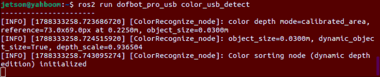
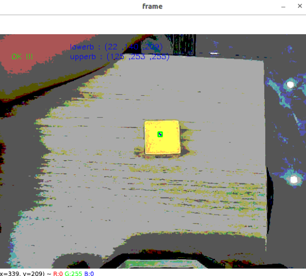
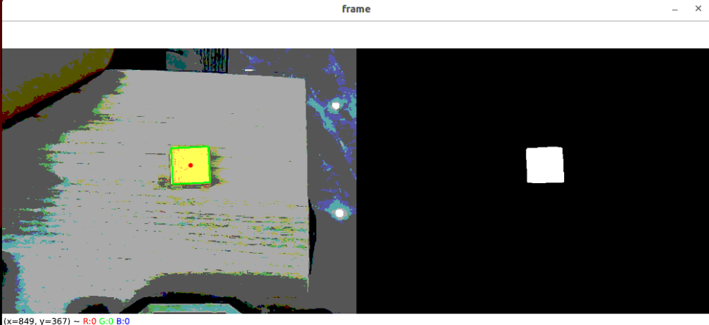
3. Operation Demo and Sorting Interaction
Place materials: Place red, green, blue, and yellow blocks in the working area directly below the robotic arm camera;
Image Display: The depth camera will display height information, which refers to the distance from the colored block to the inverse kinematics base coordinate.
Adaptive color selection and locking:
One-click quick color selection: With the image window active, press the C key to enter color selection mode;
Mouse drag selection: Use the left mouse button to drag and draw a rectangle covering the main body of the target colored block;
Automatic persistence and tracking: After releasing the left mouse button, the algorithm automatically extracts the HSV range of the object in the box and switches to tracking lock state (screen displays
Tracking: Custom). The extracted HSV data is automatically written tocustom_colorHSV.textand will be automatically loaded on next startup;
Trigger grasping and unloading:
After selecting the target block and a stable target outline appears in the image, press the spacebar (
Space);Chassis automatically fine-tunes alignment to the block, robotic arm adaptively calculates gripper angle and descends to grasp;
After successful grasping, the robotic arm automatically rotates to deliver the block to the corresponding bin, completing the automatic sorting closed-loop.
4. Core Source Code Analysis
The system is completed by "color detection decision" and "grasping execution" two nodes working in coordination:
| Camera Type | Color Detection and Localization Node | Grasping Action Execution Node |
|---|---|---|
| USB Monocular Camera | dofbot_pro_usb/color_usb_detect.py | dofbot_pro_usb/grasp_usb.py |
| 3D Depth Camera | dofbot_pro_driver/color_recognize.py | dofbot_pro_driver/grasp_desktop.py |
Regardless of which camera is mounted, the core business flow is:
HSV Color Segmentation -> Extract Bounding Box and Center -> Calculate 3D Coordinates -> Adaptively Calculate Gripper Angle -> Chassis PID Fine-tune -> IK Descent Grasping -> Rotate and Unload Based on Color ID.
The main technical implementation comparison between the two:
| Comparison Dimension | USB Monocular Camera Solution | 3D Depth Camera Solution (Nuwa-HP60C) |
|---|---|---|
| Depth Calculation Mechanism | Bounding box pixel size combined with known edge length (0.03m), use pinhole model to calculate depth | Hardware-level depth map directly indexes true physical depth at block centroid |
| Hand-Eye Spatial Compensation | Superimpose X, Y 2D plane calibration compensation | Synchronously superimpose X, Y, Z 3D omnidirectional calibration compensation |
| Chassis Alignment Distance | PID control converges to approximately 190mm | PID control converges to approximately 205mm |
| Gripper Surface Mechanism | Extract bounding box corner vectors, adaptively rotate through compute_joint5 | Extract contour vertex vectors, adaptively rotate through compute_joint5 |
4.1 USB Monocular Camera Core Source Code Analysis (color_usb_detect.py)
1. HSV Color Space Filtering and Dynamic Key Switching
Filter ambient light through Hue, Saturation, and Value, and support directly loading HSV configuration files via key:
xxxxxxxxxx# color_usb_detect.py —— One-click color selection and mouse selectionif key in [ord('c'), ord('C')]: self.Reset() # Reset state and enable box selection for color self.updata_flag = True # Mark this color selection result for persistence writing to custom_colorHSV.text2. Bounding Box Pixel Size to Physical Depth
Since monocular cameras cannot directly obtain ranging data, the algorithm uses the pixel width and height of the rotated bounding box of the colored block, combined with the 3cm standard size, to calculate depth:
xxxxxxxxxx# color_usb_detect.py —— Rotated bounding box to depthwidth_px  = 0.5 * (np.linalg.norm(p1 - p0) + np.linalg.norm(p2 - p3))height_px = 0.5 * (np.linalg.norm(p2 - p1) + np.linalg.norm(p3 - p0))
# Pinhole imaging formula: depth = focal length × real size / pixel sizez_from_w = fx * self.object_size / width_pxz_from_h = fy * self.object_size / height_pxdepth_raw = 0.5 * (z_from_w + z_from_h)
# Superimpose calibration stage scale factor depth_scaledepth = depth_raw * self.depth_scale + self.depth_bias
4.2 3D Depth Camera Core Source Code Analysis (color_recognize.py)
1. Depth Matrix Direct Index and 3D World Coordinate Computation
The depth camera receives synchronized color frames and depth frames through soft timestamps. After detecting block centroid (cx, cy), it directly extracts millimeter-level true distance from the depth matrix, and through forward kinematics and hand-eye calibration matrix, calculates the 3D world coordinates:
xxxxxxxxxx# color_recognize.py —— Centroid depth direct index and spatial transformif 0 <= cy < 480 and 0 <= cx < 640: # Direct physical depth extraction and convert to meters dist = depth_image_info[cy, cx] / 1000.0 # Combine hand-eye calibration matrix and robotic arm forward kinematics to compute base world coordinates (pose[0], pose[1], pose[2]) pose = self.compute_heigh(cx, cy, dist) # Calculate horizontal distance for chassis fine-tuning dist_detect = math.sqrt(pose[1] ** 2 + pose[0] ** 2) * 1000.02. Gripper Rotation Angle Adaptive Computation and 3D Compensation Superimposition
Calculate block inclination angle from block polygon corner difference vectors, drive joint 5 to automatically rotate and align; simultaneously superimpose the physical deviation from calibration configuration on the 3D coordinates:
xxxxxxxxxx# color_recognize.py —— Gripper alignment and grasping message packagingvx = self.corners[0][0][0] - self.corners[1][0][0]vy = self.corners[0][0][1] - self.corners[1][0][1]target_joint5 = compute_joint5(vx, vy)self.joint5.data = int(target_joint5)
pos = AprilTagInfo()pos.id = self.target_color  # Carry color ID: 1=red, 2=green, 3=blue, 4=yellowpos.x = float(self.cx)pos.y = float(self.cy)pos.z = float(dist)
# Publish target pose, trigger grasp_desktop node to execute IK grasping and bin unloadingself.pos_info_pub.publish(pos)self.TargetJoint5_pub.publish(self.joint5)
3. Color Classification Unloading Execution
After the grasping execution node receives the message carrying color ID (pos.id), it maps to different joint target angles in the move() action function, achieving delivery of different colored wooden blocks to independent physical areas, completing the automatic color sorting closed-loop.
4.3 Grasping Offset Tuning (Both Camera Models)
If position deviation occurs during actual grasping (such as missing, knocking over objects, offset left/right, or hitting the table), you can directly modify the spatial offset configuration file for the corresponding camera:
1. Where to Modify
Configuration files are located in the ~/yahboomcar_ros2_ws/dofbot_pro_ws/src/dofbot_pro_driver/config/ directory. Select based on camera type:
3D Depth Camera (Nuwa-HP60C):
offset_value.yamlUSB Camera:
usb_offset_value.yaml
2. How to Modify
The file contains offset parameters in X, Y, Z directions (unit: meters, recommended adjustment per tweak is 0.005~0.01, i.e., 5~10mm):
x_offset(forward/backward direction, positive toward vehicle front):Gripper extends too far and knocks over object decrease value (adjust smaller or set negative)
Gripper doesn't extend far enough and misses increase value (adjust larger)
y_offset(left/right direction, positive toward vehicle left):Gripper deviates right increase value (correct left)
Gripper deviates left decrease value (correct right)
z_offset(up/down height, positive toward ceiling):Gripper too high in air and can't grasp decrease value (probe deeper)
Gripper hits or scrapes table increase value (raise higher)