Welcome to ROSMASTER A1 PRO repository
17.Color Block Transport
🎨 Visual Color Recognition and Composite Transport (Color Transport)
1. Course Content
Master the high-level composite transport full process integrating Nav2 autonomous navigation, mouse ROI dynamic box selection and HSV space adaptive extraction, robotic arm real joint angle synchronization and forward kinematics solving, Ackermann chassis dedicated smooth approach control, and six-degree-of-freedom robotic arm spatial inverse kinematics grasping.
Master the dynamic mouse box selection adaptive recognition mechanism for arbitrary color materials under complex lighting conditions and the gripper servo 5 adaptive parallel offset angle alignment algorithm.
Master the full closed-loop control process from starting point autonomous cruising to operation area, target color block box selection recognition, Ackermann chassis smooth approach alignment, spatial inverse kinematics grasping, autonomous navigation to unloading point placement, and autonomous return to origin.
USB camera version only supports gripping 4 * 4 * 4 wooden blocks
2. System Architecture and Workflow
This system consists of four major modules: chassis navigation, robotic arm real state synchronization and kinematics inverse solving, HSV dynamic color picking visual solving, and Ackermann smooth approach control:
Navigate to Grasping Operation Area: The robot drives to the target color block area through Nav2 autonomous obstacle avoidance; after arrival, the buzzer beeps as a readiness prompt;
Dynamic ROI Box Selection Color Picking and Pose Synchronization: Press the
ckey in the OpenCV image window, directly box-select the target color block area with the mouse. The system automatically calculates HSV thresholds, and calls the service to obtain the robotic arm's current real joint angles, solving the real end-effector pose through forward kinematics (FK);Ackermann Chassis Dedicated Smooth Approach: Using pinhole imaging depth inverse solving and first-order low-pass filtering, through the specially designed Ackermann chassis linear and angular velocity coordinated controller, smoothly adjusts chassis heading and distance, approaching to the optimal grasping distance (~205mm);
Spatial Inverse Kinematics Grasping: After alignment and after 3 consecutive stable frames, the system automatically calculates servo 5 adaptive parallel offset angle and publishes the 3D spatial coordinates; the
grasp_transportnode executes robotic arm inverse kinematics grasping and vertically lifts and retracts to driving posture;Autonomous Transport, Unloading, and Return: Specify the unloading point in RViz; after the robot autonomously navigates and arrives at the destination, the robotic arm lowers the gripper to place the color block; subsequently, automatically plans a route back to the starting origin.
3. Preparation and Running
This case requires opening 7 terminals in sequence to start each functional node:
3.1 Start Chassis and Lidar
Run in Terminal 1 (start A1 Pro chassis driver and lidar driver):
ros2 launch yahboomcar_nav laser_bringup_launch.py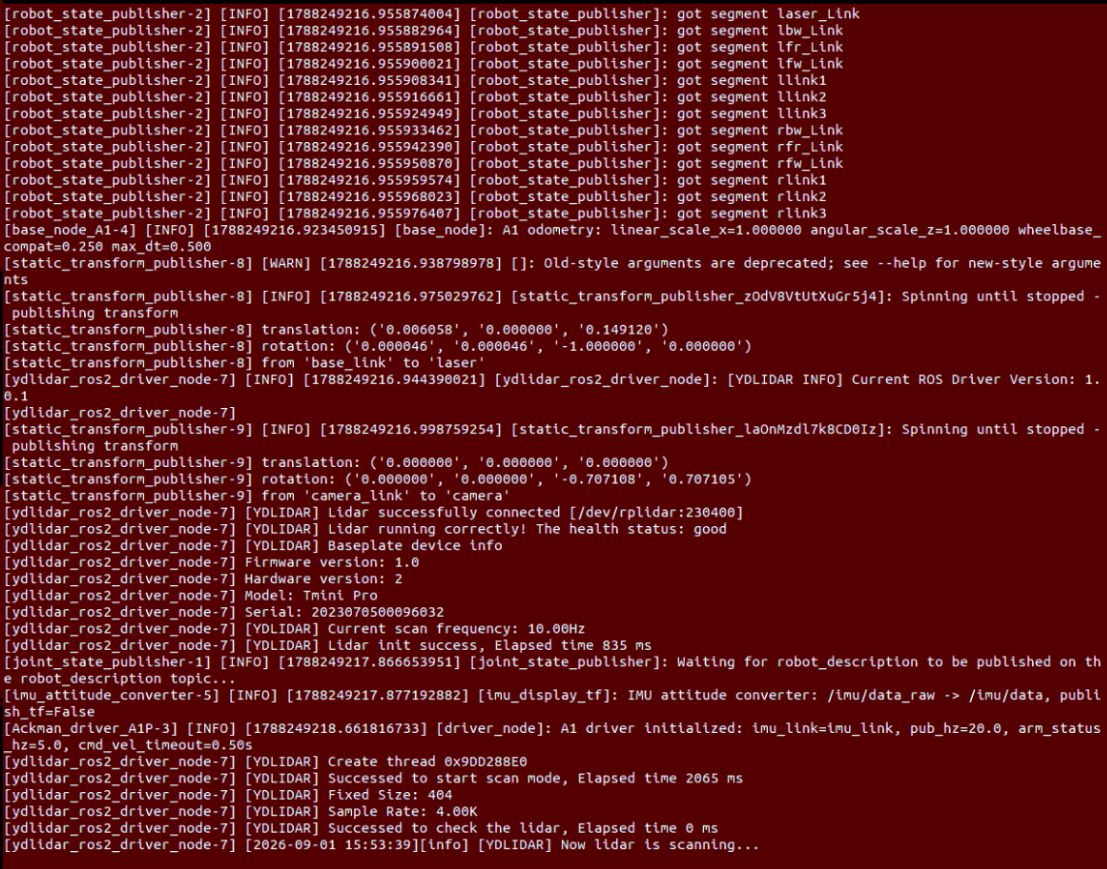
3.2 Start Robotic Arm and Camera Driver
Run in Terminal 2 (start DOFBOT Pro six-degree-of-freedom robotic arm underlying driver, forward/inverse kinematics solving service, and camera):
xxxxxxxxxxros2 launch dofbot_pro_driver camera_arm.launch.py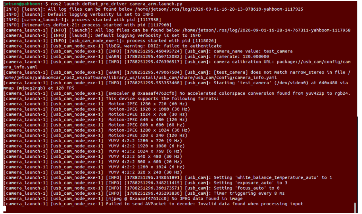
3.3 Start RViz Navigation Visualization
Run in Terminal 3 (it is recommended to open RViz on the virtual machine if the VM and robot are on the same LAN):
xxxxxxxxxxros2 launch yahboomcar_nav display_nav_launch.py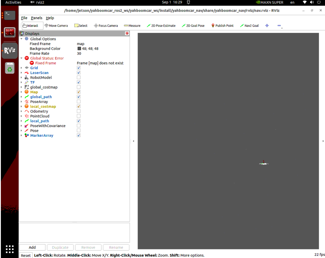
3.4 Start Nav2 Autonomous Navigation Stack
Run in Terminal 4 (start TEB local planner and global path planner):
xxxxxxxxxxros2 launch yahboomcar_nav navigation_teb_launch.py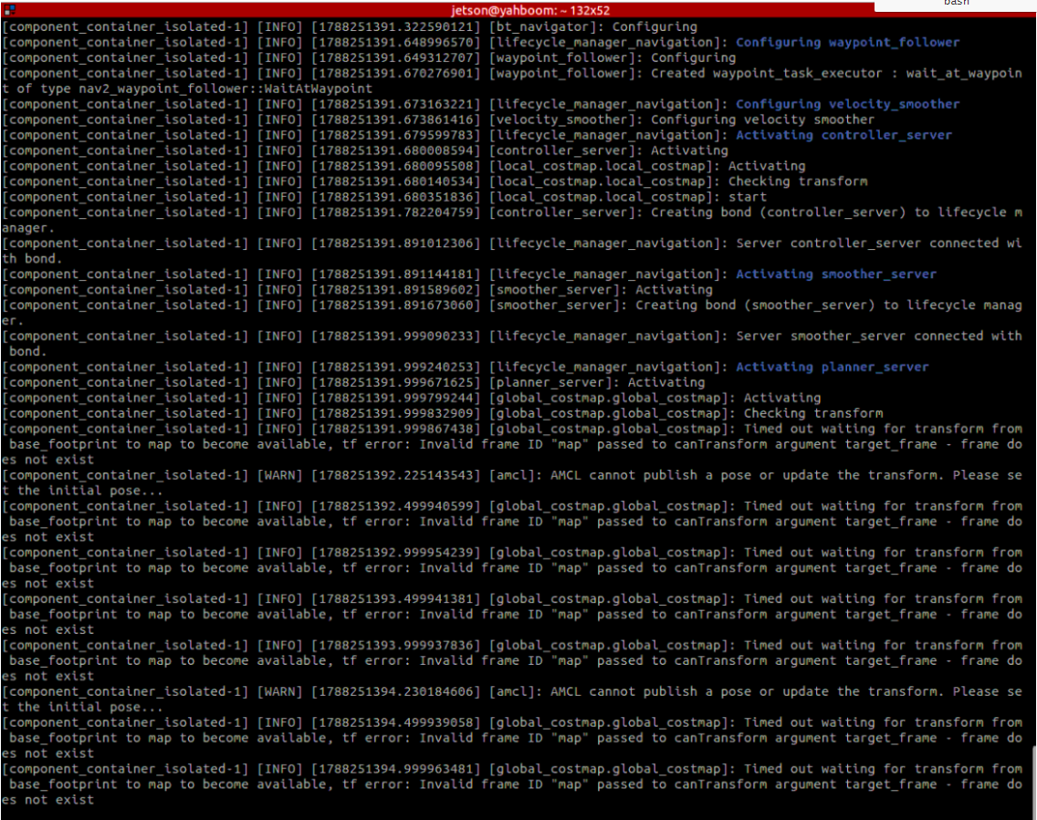
Important
Initial Pose Alignment:
Click the 2D Pose Estimate tool in the top toolbar of RViz2, click at the actual robot position on the map and drag the green arrow along the actual chassis heading direction and release, making the laser point cloud completely attach to the black obstacles on the map (this position will be automatically recorded by the system as the return origin).
3.5 Start Robotic Arm Grasping Execution Node
Run in Terminal 5 (load spatial inverse kinematics and grasping/unloading action sequence):
x# Depth camera version (Nuwa)ros2 run dofbot_pro_driver grasp_transport
# Or USB camera versionros2 run dofbot_pro_usb grasp_transport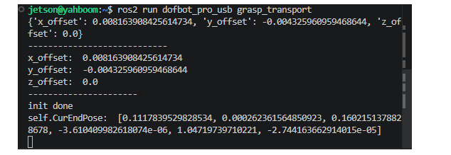
3.6 Start Navigation Status Listener and Scheduling Node
Run in Terminal 6 (monitor arrival status, origin recording, and one-key return control):
xxxxxxxxxxros2 run yahboomcar_nav get_nav2_status_V2
3.7 Start Color Recognition and Transport Master Control Node
Run in Terminal 7 (dynamic ROI box selection color picking, pose synchronization, Ackermann approach, and 3D spatial solving):
xxxxxxxxxx# Depth camera version (Nuwa)ros2 run dofbot_pro_driver color_transport
# Or USB camera versionros2 run dofbot_pro_usb color_transport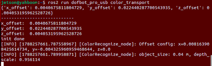
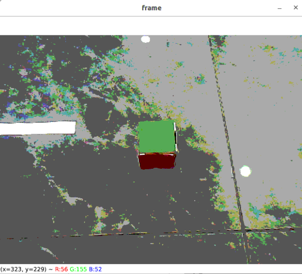
4. Operation Flow and Dynamic ROI Box Selection Interaction Description
Initial Origin Calibration: Complete initial pose alignment in RViz using
2D Pose Estimate, andget_nav2_status_V2will automatically record this point as the return baseline origin;Dynamic Mouse Box Selection Target Color (ROI Sampling): Place the target color block below the robotic arm camera field of view, and operate in the activated
frameimage window popup by OpenCV:Press keyboard key
c/C: Reset current working state and activate ROI sampling mode; terminal outputsDrag a box around the target color in the image window;Mouse left button drag box selection: In the image window, hold the left mouse button and box-select the color area of the target color block, then release;
Adaptive Recognition and Automatic Approach: The system automatically extracts HSV upper and lower limits of that area and switches to tracking state, while automatically triggering robotic arm actual pose synchronization and Ackermann chassis smooth approach;
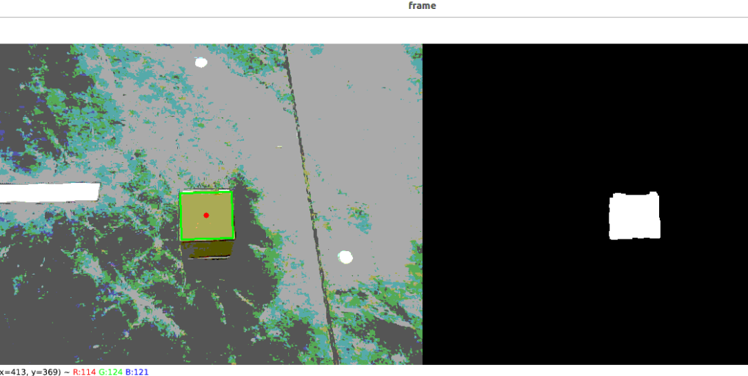
Ackermann Chassis Approach and Adaptive Grasping:
The chassis autonomously fine-tunes body and yaw angle based on color block center and depth error, smoothly moving to the target grasping distance (~205mm);
After 3 consecutive stable frames of distance measurement, the system automatically calculates servo 5 adaptive offset angle through
compute_joint5, making the gripper opening direction parallel to the color block placement edge;The robotic arm calls spatial inverse kinematics to descend and grasp the wooden block and vertically lifts and retracts to driving posture;
Autonomous Navigation Transport and Unloading:
After grasping the specified target, the robot autonomously navigates to the destination;
After arriving at the destination, the robotic arm automatically lowers the gripper to place the color block;
After unloading is complete, the robot automatically returns to the initial starting origin.
Note
When you need to end the program, press Ctrl+C in each terminal window to stop the program.
5. Core Source Code and Key Implementation Mechanism Analysis
5.1 Dynamic HSV Color Picking and Robotic Arm Pose Truth Synchronization (color_transport.py)
Source Code Path:
xxxxxxxxxx$HOME/yahboomcar_ros2_ws/dofbot_pro_ws/src/dofbot_pro_usb/dofbot_pro_usb/color_transport.py
1. Mouse ROI Dynamic Color Picking and State Machine Flow
Abandoning hard-coded HSV files that are easily affected by lighting interference, pure dynamic real-time sampling is adopted:
xxxxxxxxxxdef process(self, rgb_img, key):    # Press c key to activate new ROI sampling mode    if key in (ord('c'), ord('C')):        self.Reset()        self.sampling_active = True        self.Track_state = 'init'
    # Mouse drag box selection and HSV automatic calculation    if self.Track_state == 'init':        cv2.setMouseCallback(self.windows_name, self.onMouse, 0)        if self.select_flags and len(self.Roi_init) == 4:            cv2.rectangle(rgb_img, (self.Roi_init[0], self.Roi_init[1]), (self.Roi_init[2], self.Roi_init[3]), (0, 255, 0), 2)    elif self.Track_state == 'roi_ready':        rgb_img, self.hsv_range = self.color.Roi_hsv(rgb_img, self.Roi_init)        self.sampling_active = False        self.Track_state = 'track'        self._begin_approach() # Start pose synchronization and approach process
    # Color contour and minimum external rotating rectangle extraction    if self.Track_state == 'track' and len(self.hsv_range) != 0:        (rgb_img, binary, center, self.max_box, self.corners) = detect_color_rectangle(rgb_img, self.hsv_range)        self.cx, self.cy = center
    return rgb_img, binary
2. Robotic Arm Physical Truth Synchronization and Hand-Eye Transformation Solving
Before chassis approach, obtain the actual physical feedback angles of each robotic arm servo through service, and call the forward kinematics service to solve the end-effector's actual spatial pose, completely eliminating startup deviation:
xxxxxxxxxxdef _begin_approach(self):    # 1. Asynchronously request robotic arm's current real joint angles    future = self.actual_arm_client.call_async(ArmPosition.Request())    future.add_done_callback(self._on_actual_joints_response)
def _on_actual_joints_response(self, future):    response = future.result()    actual_joints = [float(v) for v in response.result_joints]
    # 2. Call forward kinematics (FK) to solve end-effector real spatial pose    request = ArmKinemarics.Request()    request.cur_joint1, request.cur_joint2, request.cur_joint3, request.cur_joint4, request.cur_joint5 = actual_joints[:5]    request.kin_name = 'fk'    fk_future = self.client.call_async(request)    fk_future.add_done_callback(self._on_approach_fk_response)
def _on_approach_fk_response(self, future):    response = future.result()    # Save real end-effector pose, as subsequent hand-eye calibration conversion reference    self.CurEndPos = [response.x, response.y, response.z, response.roll, response.pitch, response.yaw]    self.approach_pose_ready = True
5.2 Ackermann Chassis Dedicated Smooth Approach Control
Specially designed approach algorithm for Ackermann vehicles (front-wheel angle strongly coupled with forward linear velocity, cannot spin in place):
xxxxxxxxxxdef move_robot(self, current_dist, target_forward, target_lateral):    """Ackermann chassis smooth approach control"""    # 1. Distance error PID calculates linear velocity    distance_error = current_dist - TARGET_DIST_MM    linear_x = self.linearx_pid.compute(current_dist, TARGET_DIST_MM)    if distance_error > 0.0:        linear_x = min(APPROACH_MAX_LINEAR, max(APPROACH_MIN_LINEAR, linear_x)) # [0.025, 0.08] m/s    else:        linear_x = max(-APPROACH_MAX_REVERSE, min(-APPROACH_MIN_LINEAR, linear_x)) # Limit reverse
    # 2. Heading deviation ratio control angular velocity (Kp = 0.8)    heading_error = math.atan2(target_lateral, max(target_forward, 1e-3))    angular_z = max(-APPROACH_MAX_ANGULAR, min(APPROACH_MAX_ANGULAR, APPROACH_HEADING_KP * heading_error))
    # 3. Large turn angle deceleration collaboration (ensure front-wheel turning arc smooth convergence)    heading_scale = max(0.35, math.cos(min(abs(heading_error), math.pi / 2.0)))    linear_x *= heading_scale    self.pubVel(linear_x, 0.0, angular_z)
First-order Low-pass Distance Filtering:
self.filtered_dist_mm = 0.35 * raw_dist + 0.65 * self.filtered_dist_mm, effectively eliminating monocular distance single-frame jumping;Stable Window Criterion: When within tolerance range ($| \text{dist_error} | \le 10.0\text{ mm}$) and consecutively maintained for
APPROACH_STABLE_FRAMES = 3frames, stop and trigger robotic arm grasping.
5.3 Monocular Depth Inverse Solving and Servo 5 Adaptive Offset Angle
xxxxxxxxxxdef compute_depth_from_contour(self, box, fx, fy):    p0, p1, p2, p3 = box.astype(np.float32)    width_px = 0.5 * (np.linalg.norm(p1 - p0) + np.linalg.norm(p2 - p3))    height_px = 0.5 * (np.linalg.norm(p2 - p1) + np.linalg.norm(p3 - p0))
    # Pinhole imaging model inverse solving depth Z    z_from_w = fx * self.object_size / width_px    z_from_h = fy * self.object_size / height_px    depth_raw = 0.5 * (z_from_w + z_from_h)    return float(depth_raw * self.depth_scale + self.depth_bias)
# Calculate servo 5 adaptive offset angle (make gripper opening parallel to color block edge)vx = int(self.corners[0][0][0]) - int(self.corners[1][0][0])vy = int(self.corners[0][0][1]) - int(self.corners[1][0][1])target_joint5 = compute_joint5(vx, vy)
5.4 Robotic Arm Spatial Inverse Kinematics Grasping and Action Execution (grasp_transport.py)
Source Code Path:
xxxxxxxxxx$HOME/yahboomcar_ros2_ws/dofbot_pro_ws/src/dofbot_pro_usb/dofbot_pro_usb/grasp_transport.py
Inverse Kinematics Solving: Receives spatial coordinates
(x, y, z)and servo 5 angle fromcolor_transport, callsget_kinemaricsinverse solving service to calculate the 6 joint target pulses;Step-by-Step Safe Grasping and Unloading Actions:
Open gripper, robotic arm moves to safe transition point above the color block;
Vertically smoothly descends to the wooden block grasping height, closes gripper to clamp the color block;
Vertically lifts and retracts to safe driving posture, publishes
/grasp_donesignal;After arriving at target unloading area, lowers gripper to smoothly place the material, then triggers the robot to automatically return to the origin.
6. Core Parameter Description
| Parameter Module | Parameter Name | Current Config Value | Core Function and Physical Meaning |
|---|---|---|---|
| Material Specification | object_size | 0.04 | Standard physical side length of the color wooden block to be grasped (meters, i.e., 4cm) |
| Approach Distance | TARGET_DIST_MM | 205.0 | Robotic arm optimal grasping longitudinal benchmark working distance (millimeters) |
| Approach Tolerance | DIST_THRESHOLD_MM | 10.0 | Allowable dead zone tolerance for chassis approach arrival (millimeters) |
| Approach Linear Velocity | APPROACH_MIN/MAX_LINEAR | 0.025 / 0.08 | Ackermann chassis forward fine-tuning linear velocity range (m/s) |
| Approach Reverse Speed Limit | APPROACH_MAX_REVERSE | 0.04 | Maximum allowable reverse fine-tuning linear velocity for chassis (m/s) |
| Heading Angle Control | APPROACH_HEADING_KP | 0.8 | Approach yaw angle ratio adjustment gain |
| Approach Angular Velocity | APPROACH_MAX_ANGULAR | 0.25 | Ackermann chassis turning maximum angular velocity (rad/s) |
| Distance Filtering | APPROACH_FILTER_ALPHA | 0.35 | Distance first-order low-pass filter coefficient (suppress monocular distance jitter) |
| Stable Frame Count | APPROACH_STABLE_FRAMES | 3 | Consecutive stable frame threshold required for arrival judgement |
| Offset Calibration | x/y/z_offset | Dynamically loaded | Spatial micro-adjustment compensation of gripper and material grasping geometric center (YAML configuration) |