Welcome to ROSMASTER A1 PRO repository
6.Robot URDF Model
🧊 Robot URDF Model
1. Course Introduction
View the A1 Pro 3D URDF robot model in real-time in RViz2. The model pose is driven by IMU data in real-time — pick up the robot and flip or tilt it arbitrarily, and the 3D model in RViz2 will follow the motion in real-time, intuitively displaying the coordinate systems of various sensors, the wheeled chassis, and the joint structure of the 6-DOF robotic arm.
🎯 Course Objectives
Understand the basic concepts and structural components of URDF models
Master the visualization method of IMU-driven robot 3D pose in RViz2
Understand robotic arm joint state feedback (
joint_state_publisher) and TF coordinate transform treeMaster the usage of visualization launch parameters (
pose_source,gui, camera type)
2. Demonstration Examples
2.1 Launch Model Visualization
Run the following command in the terminal:
ros2 launch dofbot_pro_description display_A1pro.launch.py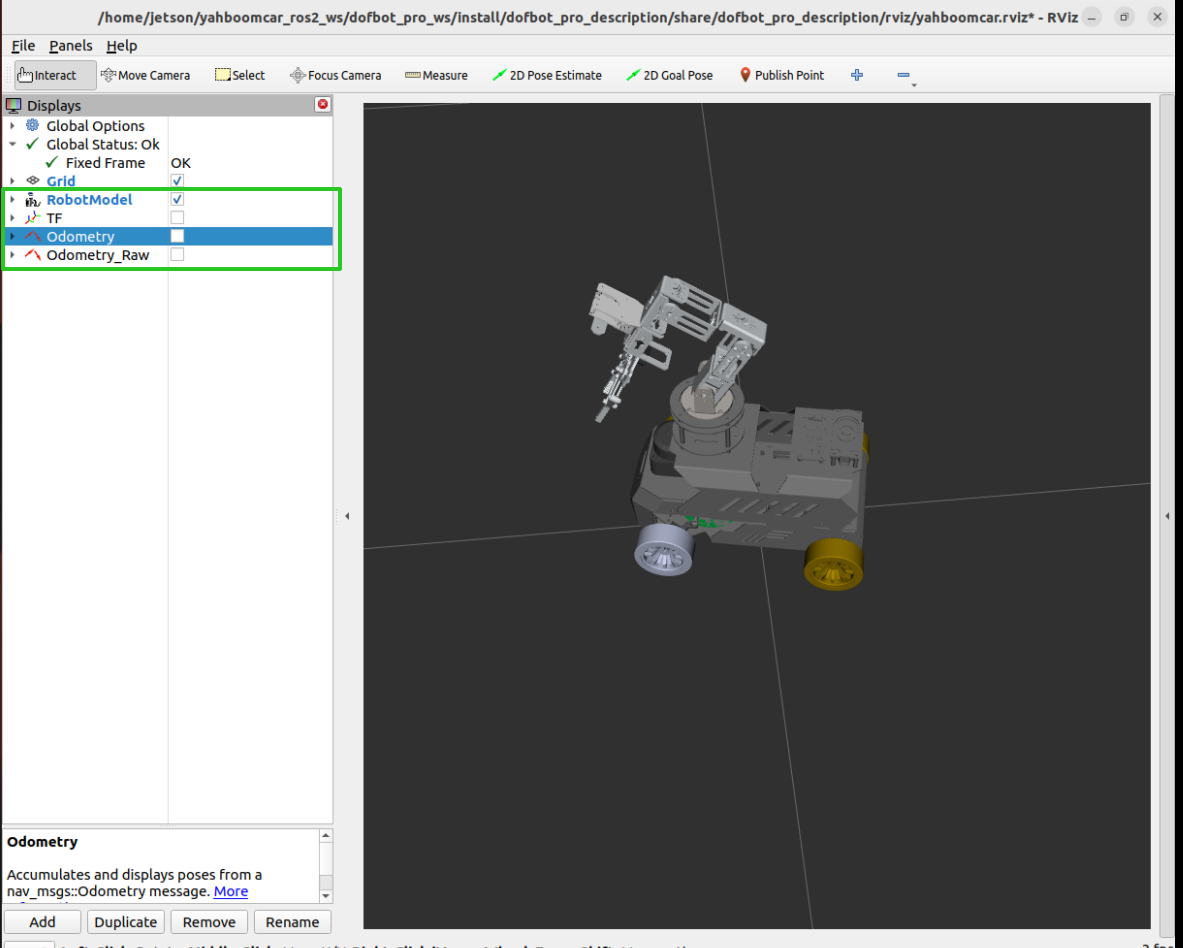
Tip
After launching, RViz2 will automatically load the A1 Pro 3D model and coordinate system configuration. If there are unwanted display layers in the interface, you can manually check/uncheck them in the left-hand Displays panel.
2.2 Operation and Effect Description
After launching, RViz2 will display the complete 3D structure of A1 Pro, including the Ackerman chassis, 6-DOF robotic arm, and depth camera:
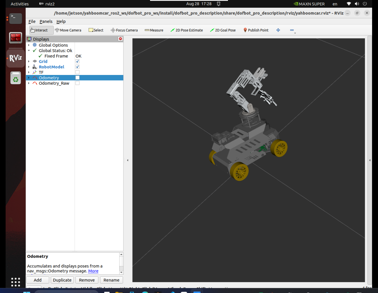
IMU 3D Pose Tracking:
In default mode (
pose_source:=imu), pick up the robot and flip, pitch, or rotate it arbitrarily in the air, and the model in RViz2 will synchronously follow with a 1:1 tilt and rotation (supporting full 3D pose with Roll/Pitch/Yaw).
Robotic Arm Joint State Real-time Synchronization:
The low-level driver node (
Ackman_driver_A1P) reads each servo angle in real-time and publishes to the/arm_status/arm_jointtopic.joint_state_publishersubscribes to this state and updates the TF coordinate transforms for each joint of the robotic arm, keeping the arm pose in the 3D model synchronized with the physical entity.
GUI Slider Simulation Control:
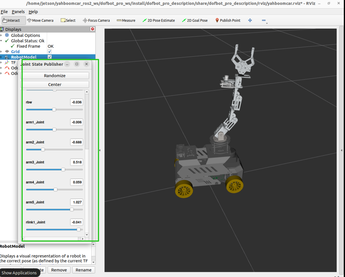
You can pass the
gui:=trueparameter to launch the graphical slider control panel. When not connected to a real robotic arm or when debugging joints, you can manually drag the sliders to observe each joint's movement:
xxxxxxxxxxros2 launch dofbot_pro_description display_A1pro.launch.py gui:=true
3. Launch Parameters Description
display_A1pro.launch.py supports rich parameter configuration to adapt to different debugging scenarios:
| Parameter | Default | Options | Description |
|---|---|---|---|
pose_source | imu | imu / ekf | Pose data source: imu mode displays 3D full-pose flipping; ekf mode displays planar fused odometry |
gui | false | true / false | Whether to enable GUI slider panel (when true, sliders simulate joints; when false, uses real robotic arm feedback) |
start_hardware | true | true / false | Whether to start low-level hardware driver. If bringup is already running in another terminal, set to false |
fixed_frame | odom | string | RViz2 fixed reference frame name |
model | auto-match | file path | URDF model path (by default, automatically selects nuwa or usb camera model based on system environment variable CAMERA_TYPE) |
4. URDF Basics
4.1 What is URDF?
URDF (Unified Robot Description Format) is the standard file format in ROS for describing robot models in XML format. It defines the robot's geometric appearance (Mesh), joint connections (Joint), collision bodies (Collision), and physical inertial properties (Inertial).
4.2 Core Tags
| Tag | Description |
|---|---|
<link> | Link — Rigid body parts of the robot (such as chassis, robotic arm links, wheels, etc.) |
<joint> | Joint — Defines the connection relationship and motion constraints between two links (such as rotation, translation, or fixed) |
<visual> | Visual rendering appearance (supports STL/DAE 3D mesh models and color materials) |
<collision> | Collision detection geometry (usually simplified to improve physics engine computation efficiency) |
<inertial> | Dynamics properties (mass, moment of inertia matrix) |
4.3 Joint Types
| Type | Description |
|---|---|
fixed | Fixed joint, child link is rigidly fixed to parent link and cannot move |
revolute | Revolute joint with maximum/minimum angle limits (robotic arm joints 1~6 are all revolute) |
continuous | Continuous rotation joint without angle upper/lower limits (commonly used for wheel rotation) |
prismatic | Prismatic joint, linear translation along a specified axis |
4.4 A1 Pro Coordinate Transform Tree (TF Tree)
The core coordinate system hierarchy of the A1 Pro robot is as follows:
xxxxxxxxxxodom (odometry reference frame)└── base_footprint (chassis ground projection reference)└── base_link (chassis center reference)├── imu_link (IMU sensor coordinate system)├── laser_frame (LiDAR coordinate system)├── camera_link (depth camera coordinate system)└── arm1_Link (robotic arm base rotation)└── arm2_Link (upper arm pitch)└── arm3_Link (forearm pitch)└── arm4_Link (wrist pitch)└── arm5_Link (wrist rotation)└── rlink1_Link (end effector gripper)
Tip
You can run the following command in a new terminal to generate and view the complete real-time TF tree of the current system:
xxxxxxxxxxros2 run tf2_tools view_framesevince frames.pdf5. Source Code Implementation Principle Analysis
5.1 IMU Pose Computation and TF Publishing (imu_display_tf.py)
In pose_source:=imu mode, the imu_attitude_converter node is responsible for converting the IMU sensor's pose and publishing it as the odom → base_footprint coordinate transform:
xdef imu_callback(self, msg: Imu): # Extract IMU raw quaternion and convert to Euler angles (Roll, Pitch, Yaw) roll, pitch, yaw = quaternion_to_euler( msg.orientation.x, msg.orientation.y, msg.orientation.z, msg.orientation.w )
# Adapt to A1P chassis mounting orientation: swap Pitch and Roll, invert Yaw x, y, z, w = euler_to_quaternion(pitch, roll, -yaw)
# Publish /imu/data for other algorithm nodes to use converted = Imu() ... self.imu_publisher.publish(converted)
# When publish_tf is True, publish odom → base_footprint 3D pose transform if self.publish_tf: transform = TransformStamped() transform.header.frame_id = self.fixed_frame transform.child_frame_id = self.base_frame transform.transform.translation.x = self.position[0] transform.transform.translation.y = self.position[1] transform.transform.translation.z = self.position[2] transform.transform.rotation.x = x transform.transform.rotation.y = y transform.transform.rotation.z = z transform.transform.rotation.w = w self.tf_broadcaster.sendTransform(transform)Note
There is an axis mapping relationship between the physical mounting orientation of the chassis IMU chip and the ROS standard coordinate system (REP-103). The node internally handles Roll/Pitch swapping and Yaw negation to ensure that the robot's tilting up, tilting, and turning motions are completely consistent with the 3D model in RViz.
6. Source Code and Resource Path Reference
| File Type | Relative Path | Description |
|---|---|---|
| Launch File | dofbot_pro_ws/src/dofbot_pro_description/launch/display_A1pro.launch.py | Model visualization and hardware scheduling launch script |
| Ansearch Camera URDF | dofbot_pro_ws/src/dofbot_pro_description/urdf/yahboomcar_A1pro_nuwa.urdf | Robot model file equipped with Nuwa depth camera |
| USB Camera URDF | dofbot_pro_ws/src/dofbot_pro_description/urdf/yahboomcar_A1pro_usb.urdf | Robot model file equipped with USB camera |
| RViz Config File | dofbot_pro_ws/src/dofbot_pro_description/rviz/yahboomcar.rviz | Preset model display viewport and layer configuration |
| IMU Pose Conversion Source | yahboomcar_ws/src/yahboomcar_bringup/yahboomcar_bringup/imu_display_tf.py | IMU 3D pose computation and TF publishing node |