Welcome to ROSMASTER A1 PRO repository
2.Road Network Annotation
🗺️ Building Pose Maps and Road Network Annotation
1. Course Content
Before road network planning and navigation, robots need two foundational components:
High-precision spatial map and pose graph: Use LiDAR and Cartographer SLAM to scan the environment, generating a 2D grid map (
map.yaml/map.pgm) and a pose graph (map.pbstream) for fast relocalization;Topological road network description file (
map.geojson): On the completed map, use the visualization toolRoute Toolto mark road points (Node) and connected road segments (Edge), set one-way or two-way traffic rules, and save.
Note
Before annotating the road network
.geojsonfile, you must have at least one environment grid map.Saving the Cartographer pose map (
.pbstream) enables fast and precise global relocalization during subsequent navigation, completely avoiding cumulative drift from wheel slip.This tutorial uses the standard working path (user path
~/map) as the main demonstration, while being compatible with various industrial PC platforms.
2. Phase 1: Building Grid Map and Pose Map
2.1 Check ROS 2 Environment Configuration on Master and Slave Machines
Click the app on the desktop to configure robot parameters

Mainly configure two parts: ROS 2 communication middleware and Domain ID. Other configurations will be set up when needed later.
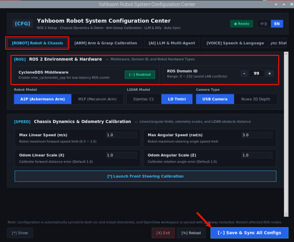
Click Save and Sync Configuration. Exit after configuration is complete.
Tip
Before mapping, you can place some cardboard boxes or wooden blocks outside the road boundaries on the map as contour reference objects. This helps the robot's LiDAR have sufficient geometric features for matching during mapping and navigation.
2.2 Start Cartographer Mapping
This phase requires opening 3 terminals for collaborative mapping:
Terminal 1: Start Robot Chassis and Cartographer Mapping Node (Robot Side)
xxxxxxxxxxros2 launch yahboomcar_nav map_cartographer_launch.py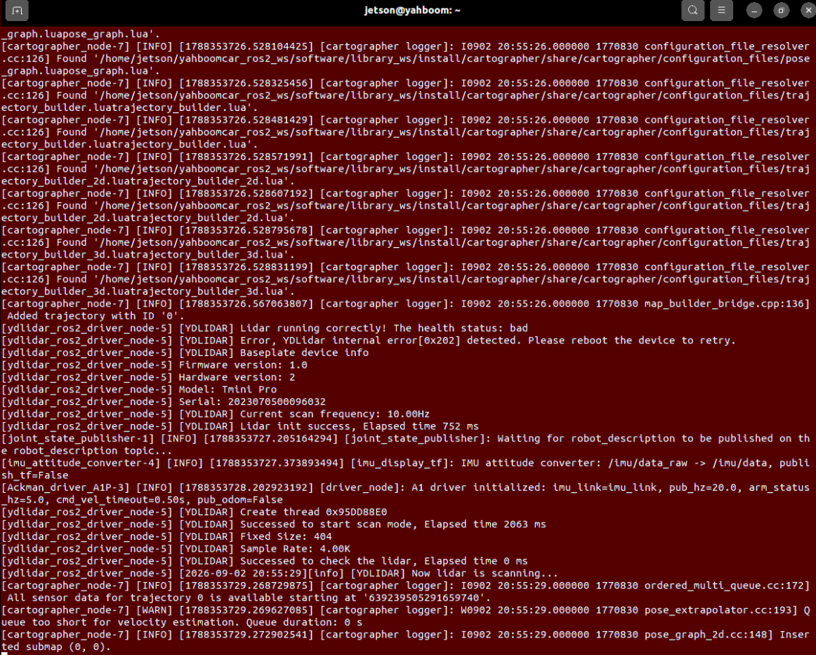
Terminal 2: Start RViz Mapping Visualization (RDK board and Raspberry Pi board recommend using the virtual machine side)
xxxxxxxxxxros2 launch yahboomcar_nav display_map_launch.py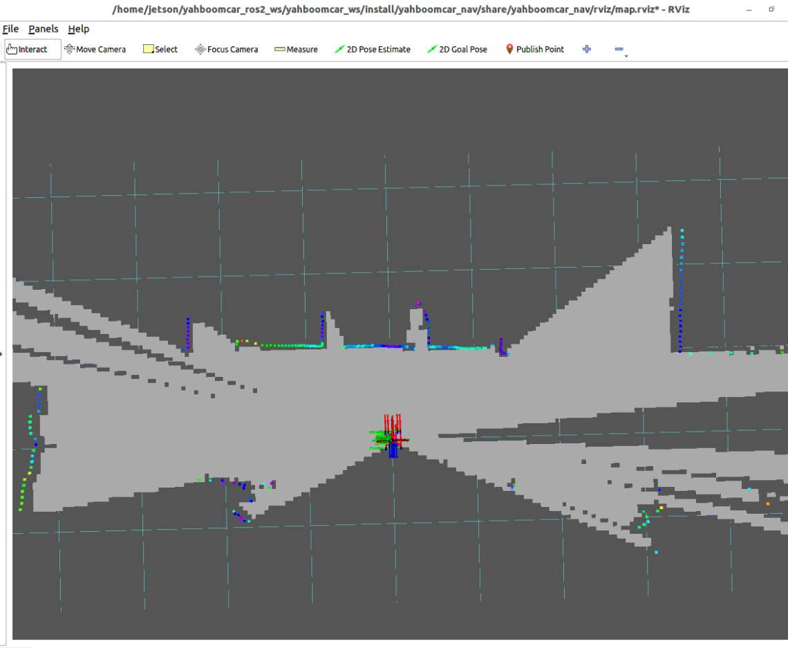
Terminal 3: Start Keyboard Control Node
xxxxxxxxxxros2 run yahboomcar_ctrl yahboom_keyboard2.3 Save Grid Map and Pose Map
After mapping is complete, execute the save commands in sequence in the terminal:
1. Save 2D Grid Map (map.yaml + map.pgm)
xxxxxxxxxx# Save map to ~/mapros2 launch yahboomcar_nav save_map_launch.py map_save_dir:=/home/jetson/map map_name:=map# Raspberry Piros2 launch yahboomcar_nav save_map_launch.py map_save_dir:=/root/map map_name:=map# RDK boardros2 launch yahboomcar_nav save_map_launch.py map_save_dir:=/home/sunrise/map map_name:=mapWhen the terminal prints Map saved successfully, the 2D map has been saved successfully:
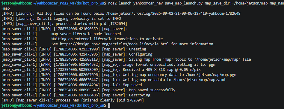
2. Save Cartographer Pose Map (map.pbstream)
Through ROS 2 service call, write the current trajectory map and submap constraints to the .pbstream file:
xxxxxxxxxx# RDK X5 system (sunrise user)ros2 service call /write_state cartographer_ros_msgs/srv/WriteState "{filename: '/home/sunrise/map/map.pbstream'}"
# If master machine is jetson userros2 service call /write_state cartographer_ros_msgs/srv/WriteState "{filename: '/home/jetson/map/map.pbstream'}"
# pi5 userros2 service call /write_state cartographer_ros_msgs/srv/WriteState "{filename: '/root/map/map.pbstream'}"
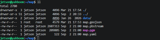
Map files are saved in ~/map or the specified directory by default, containing three core assets: map.yaml, map.pgm, and map.pbstream:
3. Phase 2: Road Network Annotation (Route Annotation)
3.1 Start Global Localization and Annotation Tools
When annotating the road network, the system needs to know the robot's precise coordinates in the global map in real time. Therefore, first start the chassis driver and navigation localization node.
Terminal 1: Start Robot Chassis and LiDAR Driver (Robot Side)
xxxxxxxxxxros2 launch yahboomcar_nav laser_bringup_launch.py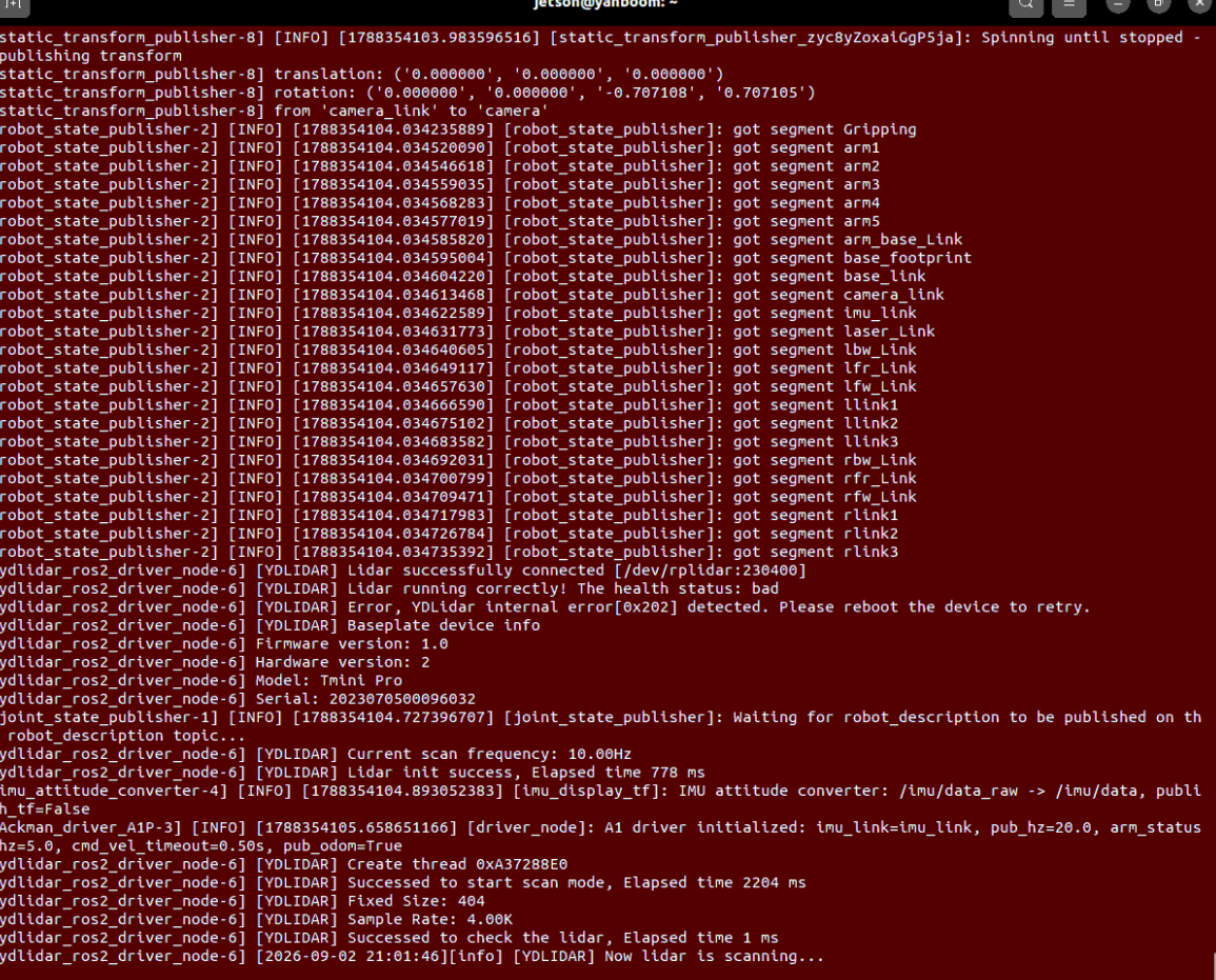
Terminal 2: Start Docker Container Environment
If using the ros2_kilted container environment:
xxxxxxxxxx# Quick start commandbringup_ros2kilted# Enter container terminalexec_ros2kilted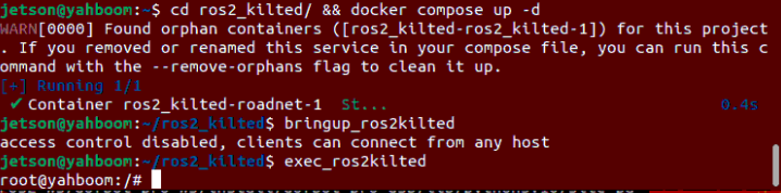
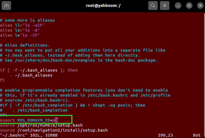
Enter in the terminal to ensure the container and host machine ROS_DOMAIN_ID are consistent:
xxxxxxxxxxvi ~/.bashrc
Terminal 3: Start Road Network Annotation RViz Tool Panel (Road Network Side)
Run the annotation interface on the board/virtual machine or inside the container: (RDK and Raspberry Pi boards need to start RViz with integrated tools on the virtual machine)
xxxxxxxxxx# Start annotation tool standalone panelros2 launch road_net_route route_tool.launch.pyThis demonstrates the Orin board.
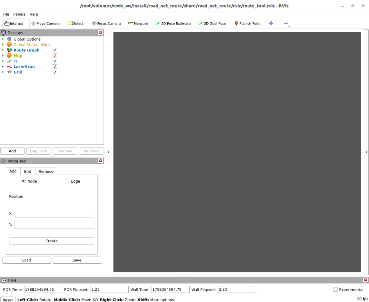
Terminal 4: Start Navigation Base to Load Map (Robot Side)
xxxxxxxxxx# RDK X5 systemros2 launch yahboomcar_nav navigation_teb_launch.py map:=/home/sunrise/map/map.yaml
# Or Jetson master machineros2 launch yahboomcar_nav navigation_teb_launch.py map:=/home/jetson/map/map.yaml
# Or pi5 master machineros2 launch yahboomcar_nav navigation_teb_launch.py map:=/root/map/map.yaml
In RViz, use the 2D Pose Estimate button in the toolbar to give the robot an initial pose on the map, so that the LiDAR scan contour precisely aligns with the black and white obstacle edges on the map:
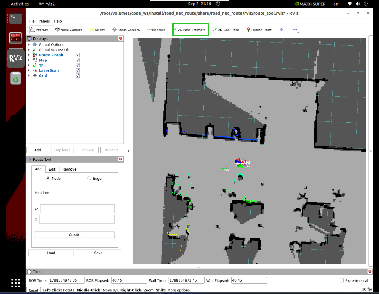
3.2 Interactively Add Road Points (Nodes)
Click the
Publish Pointtool in the RViz top toolbar;Move the mouse to the robot's current center position (or the center of the passage you want to set as a station on the map), and left-click the mouse;
The
Route Toolpanel in the lower left will automatically read and fill in the X/Y coordinates of that point. ClickCreateto create the road point:
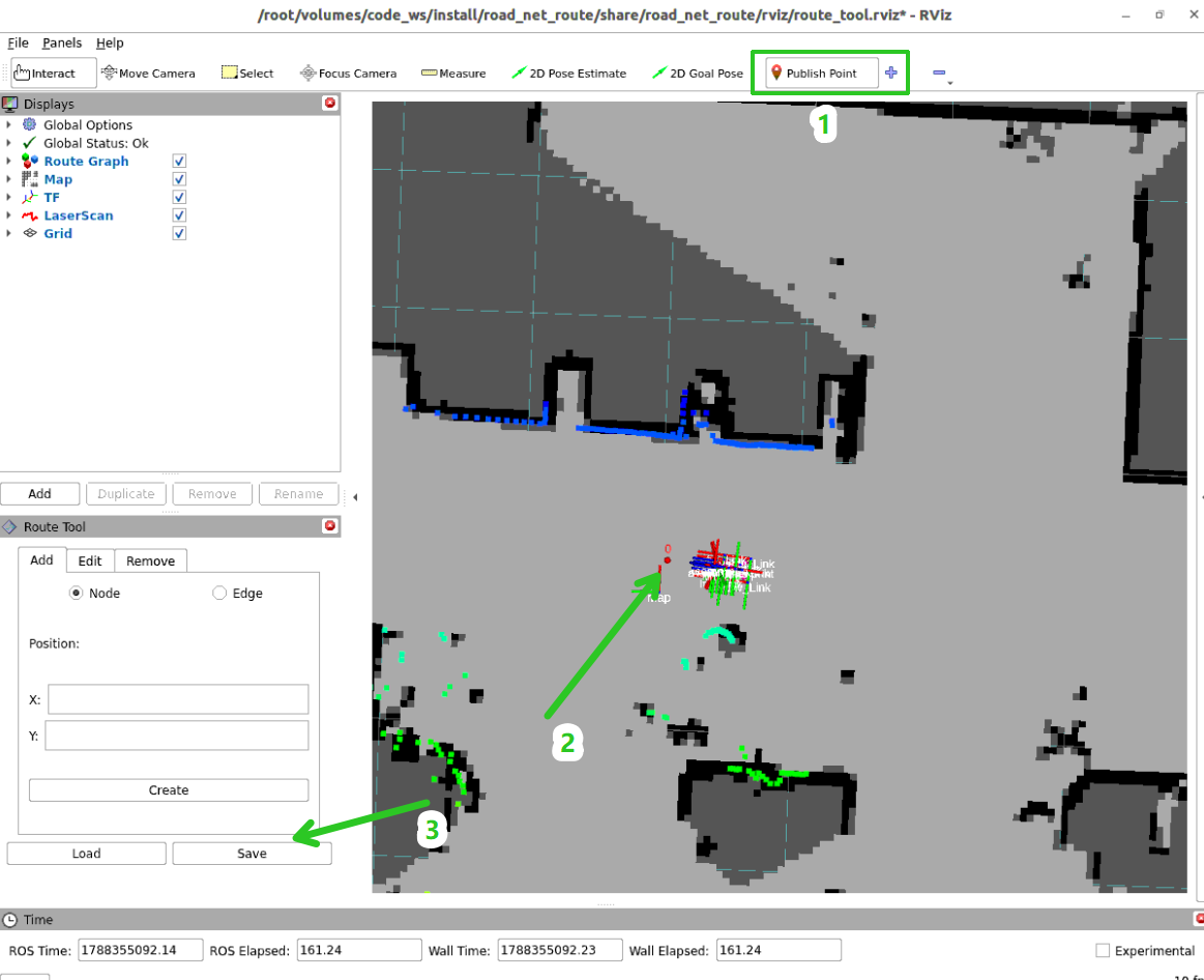
Use keyboard control to move the robot to the next location that needs a road point marker, and repeat clicking
Publish Point->Create:xxxxxxxxxxros2 run yahboomcar_ctrl yahboom_keyboard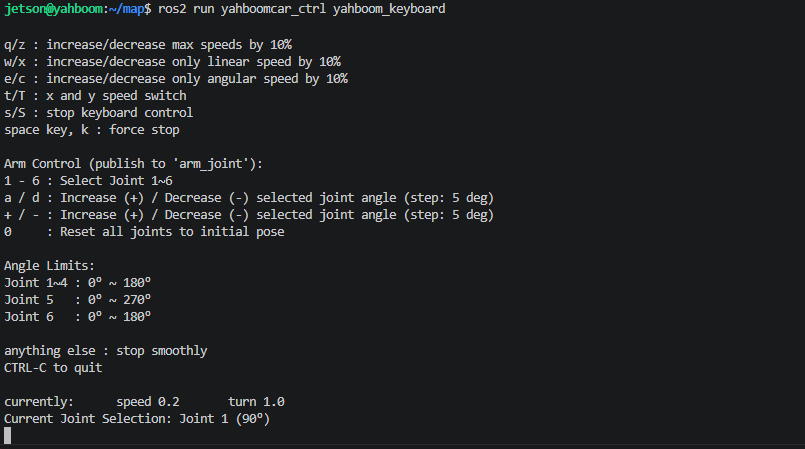
Warning
If the LiDAR contour becomes slightly misaligned with the map due to wheel slip during point annotation, you can manually use 2D Pose Estimate in RViz. After the localization converges and matches, continue annotating the next road point.
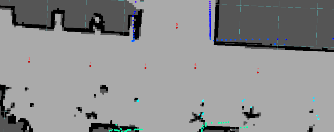
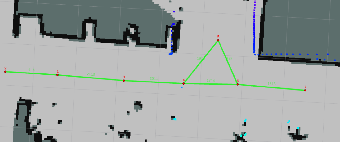
Annotate all target key stations in sequence (such as road points 0, 1, 2, ...):
3.3 Interactively Add Directed Edges (Edges)
The road network is a typical directed topological graph structure. Only when "edges" are connected between points can the robot travel between them.
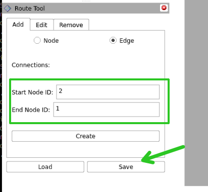
Switch to the
Edgepage at the top of theRoute Tooltab;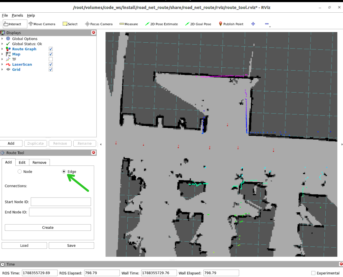
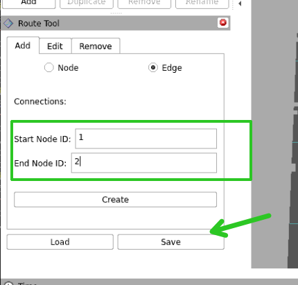
Enter the starting point number in
Start Node ID(such as 1), enter the ending point number inEnd Node ID(such as 2), and clickCreate:
Important
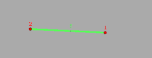
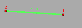
Special Note: Edges have directionality! Creating 1 -> 2 means this is a one-way street (only allowed to travel from 1 to 2, reverse driving prohibited). If this road allows two-way traffic, you must create another 2 -> 1 edge!
Create reverse edges for two-way traffic lanes:
Complete the connections for all passable road segments in the site in sequence:
3.4 Save Road Network Description File (.geojson)
Click the
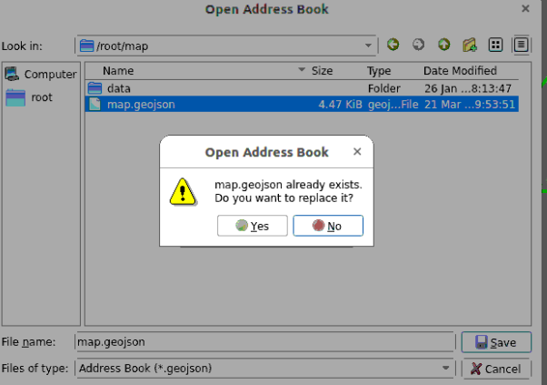
Savebutton in theRoute Toolpanel;In the pop-up file save dialog, name the file
map.geojson(recommended to save in the same~/map/directory as the grid map):
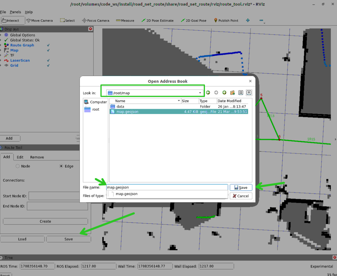
Select overwrite.
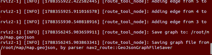
The terminal prints the JSON record indicating successful save:
Tip
If the map.geojson was annotated and saved on the virtual machine side, use scp or a shared folder to copy the file to the robot-side host directory:
xxxxxxxxxx# RDK X5cd ~/mapscp map.geojson sunrise@<robotIP>:/home/sunrise/map/4. Loading and Modifying Existing Road Networks
If the site layout changes later and you need to add, delete, or adjust road points and edges, there is no need to rebuild from scratch:
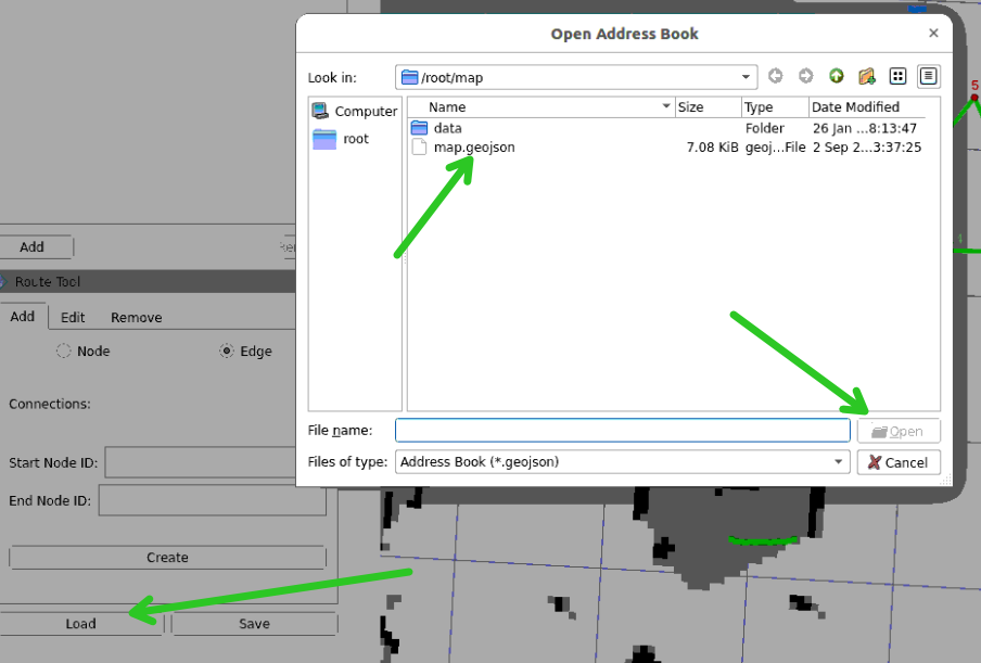
Start the
Route Toolinterface;Click the
Loadbutton and select the previously savedmap.geojsonto open:
Click
Editto re-enter coordinates to modify road point locations, or update edge endpoints;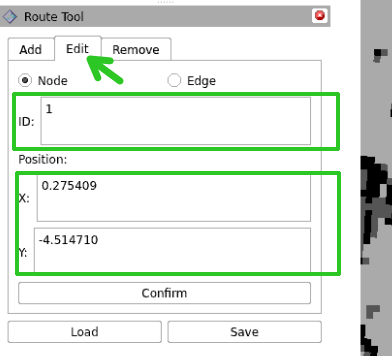
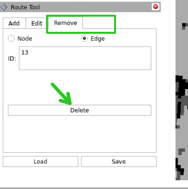
Click
Removeto directly remove misannotated road points or obsolete road segments. After modifications are complete, clickSaveto overwrite and save.
5. Core Source Code Analysis: GeoJSON Data and RoadNetwork Parser
Source code reference: code_ws/src/road_net_route/road_net_route/roadnet.py
5.1 GeoJSON File Standard Format
The .geojson generated by the annotation tool follows the standard geographic information structure, containing the two basic elements of the road network: nodes (Point) and road edges (LineString):
xxxxxxxxxx{ "type": "FeatureCollection", "features": [ { "type": "Feature", "geometry": { "type": "Point", "coordinates": [1.25, -0.85] }, "properties": { "id": 1 } }, { "type": "Feature", "geometry": { "type": "LineString", "coordinates": [[1.25, -0.85], [2.10, -0.85], [3.10, -0.85]] }, "properties": { "start_id": 1, "end_id": 2, "bidirectional": true } } ]}5.2 Python-side Road Network Graph Loading and Topology Construction Logic
When the system starts, the RoadNetwork class in roadnet.py fully loads this file and converts it into an in-memory data structure that graph algorithms can operate on:
xxxxxxxxxx# roadnet.py —— Node and edge loading processdef _load(self, roadnet_file: str):    with open(roadnet_file, 'r') as f:        data = json.load(f)
    # Phase 1: Extract all Point features to build topology node dictionary    for feature in data['features']:        if feature['geometry']['type'] == 'Point':            node_id = self._parse_node_id(feature['properties'].get("id"))            if node_id is None:                continue            x, y = feature['geometry']['coordinates']            self.node_coords.append([x, y])            self.node_ids.append(node_id)            self.node_coords_by_id[node_id] = (x, y)            self.adjacency.setdefault(node_id, {})
    # Phase 2: Extract LineString features to build weighted adjacency list and edge geometry polylines    for feature in data['features']:        if feature['geometry']['type'] not in ('LineString', 'MultiLineString'):            continue        # Parse edge start and end points (supports multiple compatible aliases like start_id/end_id, source/target)        start_id, end_id = self._resolve_edge_endpoints(feature)        if start_id is None or end_id is None or start_id == end_id:            continue
        # Calculate geometric Euclidean distance between two points as the topology cost weight        weight = self._edge_weight(start_id, end_id)        self.adjacency.setdefault(start_id, {})[end_id] = weight        # If it is a bidirectional edge, add reverse adjacency relationship        self.adjacency.setdefault(end_id, {})[start_id] = weight
        # Save the continuous polyline point set corresponding to this edge for subsequent path interpolation to generate smooth trajectories        geometry_points = self._edge_geometry_points(feature['geometry'], start_id, end_id)        if geometry_points:            self.edge_geometry_by_nodes[(start_id, end_id)] = geometry_points            self.edge_geometry_by_nodes[(end_id, start_id)] = list(reversed(geometry_points))
Note
RoadNetwork not only stores the topological connectivity relationships between points (used for fast Dijkstra shortest path finding), but also fully caches the physical curve geometry points of each edge (edge_geometry_by_nodes). This enables curved roads to be smoothly sampled into dense navigation paths, rather than generating rigid polylines.