yahboom
HomeTutorialsProduct
Solution
Blog
Online Store
About Us
EN/中文
Store
ROSMASTER A1 PRO📖
00.Configuration and Operation Guide
  • 0. Unboxing and Review
  • 1.Assembly Videos
  • 2.User Manual
  • 3.Enter Docker (For Raspberry Pi)
  • 4.A1Pro Front Wheel Servo Calibration
  • 5.USB Camera Calibration
  • 6.Depth Camera Calibration
  • 7.FAQ
  • 8.Desktop Configuration Center and Remote Control Guide
01.Chassis Control Course
  • 1.Robot Information Publishing
  • 2.Robot Handle Control
  • 3.Robot Keyboard Control
  • 4.Linear Velocity Calibration
  • 5.Angular Velocity Calibration
  • 6.Robot URDF Model
  • 7.Robot EKF State Estimation
02.Lidar Course
  • 1.Lidar Introduction and Use
  • 2.Lidar Obstacle Avoidance
  • 3.Lidar Following
  • 4.Lidar Patrol
  • 5.GMapping-SLAM Mapping
  • 6.Cartographer-SLAM Mapping
  • 7.Slam-Toolbox Mapping
  • 8.Lifelong Mode Mapping
  • 9.Navigation2 Single Point Navigation
  • 10.Navigation2 Multi Point Navigation
  • 11.Cartographer Relocalization Navigation
  • 12.Slam-Toolbox Localization Navigation
  • 13.Synchronous Mapping And Navigation
  • 14.Aruco Visual Relocalization Navigation
  • 15.Mobile App Mapping And Navigation
  • 16.AprilTag Transport
  • 17.Color Block Transport
03.USB Camera-Depth Camera Course
  • 1.USB Camera Introduction
  • 2.USB Camera Intrinsic Calibration
  • 3.Nuwa-HP60C Camera Introduction (Depth Camera Only)
  • 4.Depth Camera Distance Measurement (Depth Camera Only)
  • 5.Depth Pseudo Color Image (Depth Camera Only)
  • 6.Block Volume Calculation (Depth Camera Only)
  • 7.Edge Detection (Depth Camera Only)
  • 8.RTAB-Map SLAM Mapping (Depth Camera Only)
  • 9.RTAB-Map Navigation (Depth Camera Only)
04.Robotic Arm and 3D Space Gripping Course
  • 0.Robotic Arm Basic Usage
  • 1.Robotic Arm Kinematics
  • 2.Robotic Arm Chassis Coordination Control
  • 3.AprilTag ID Sorting
  • 4.AprilTag Height Anomaly Sorting
  • 5.AprilTag Tracking and Grasping
  • 6.Color Block Sorting
  • 7.Color Block Height Anomaly Sorting
  • 8.Color Block Tracking and Grasping
  • 9.Wood Block Shape Sorting
  • 10.KCF Tracking and Grasping Objects
  • 11.Mediapipe Gesture ID Sorting AprilTag
  • 12.Mediapipe Gesture Height Sorting AprilTag
  • 13.Desktop Tracking and Grasping AprilTag
  • 14.3D Spatial Tracking AprilTag
  • 15.Line Following Obstacle Clearing
  • 16.Transformer Model Tracking Algorithm
05.Road Network Planning and Navigation
  • 1.Introduction To Road Network Planning
  • 2.Road Network Annotation
  • 3.Planning And Navigation Between Waypoints
  • 4.Road Network Navigation In Any Pose
  • 5.Path Re-planning
06.OpenClaw Basic Course
  • 1.Introduction to OpenClaw
  • 2.OpenClaw Core Concepts
  • 3.OpenClaw API-KEY Configuration
  • 4.OpenClaw Switch Models
  • 5.OpenClaw System Prompt Words
  • 6.OpenClaw Common CLI Commands
07.OpenClaw Interaction Method
  • 1.OpenClaw Webchat Interaction
  • 2.OpenClaw Tui Interaction
  • 3.OpenClaw Voice Dialogue Interaction
  • 4.OpenClaw WhatsApp Interaction
08.OpenClaw Development
  • 1.OpenClaw Connecting to Robot MCP Service
  • 2.Robot CLI Command Tool
  • 3.robot-control plugin tool
  • 4.reply-bridge plugin tool
  • 5.OpenClaw Multimodal Vision
  • 6.OpenClaw Chassis Control
  • 7.OpenClaw Robotic Arm Control
  • 8.OpenClaw Skills Development
  • 9.OpenClaw Scheduled Tasks
  • 10.OpenClaw Multi-Agent Intelligent Agent
  • 11.OpenClaw Active Interaction
  • 12.OpenClaw Vector Memory
09.OpenClaw Embodied Intelligent Application
  • 1.OpenClaw Target Tracking
  • 2.OpenClaw Arm Tracking And Grasping
  • 3.OpenClaw Arm Fixed-point Placement
  • 4.OpenClaw Waste Sorting
  • 5.OpenClaw SLAM Mapping And Navigation
  • 6.OpenClaw Navigation Transport
  • 7.OpenClaw AprilTag Grasping
  • 8.OpenClaw Color Line Patrol
  • 9.OpenClaw Visual Distance Measurement
10.OpenClaw Scenario Sandbox
  • 1.Map Description and Prop Placement
  • 2.Build Sand Table Map
  • 3.Visual Relocation Markers
  • 4.Map Mapping Markers
  • 5.OpenClaw Scenario Sandbox Comprehensive Case
11.AI Model Basics
  • 1.AI Large Model Types and Principles
  • 2.RAG Retrieval Enhancement and Model Training Samples
  • 3.Embodied Intelligent Robot System Architecture
  • 4.Embodied Intelligent Functions Core Source Code
12.AI Model Development
  • 1.Register a Model Service Provider Aaccount
  • 2.Configuring API-KEY
  • 3.Introduction to Dify
  • 4.Basic Dify Features
  • 5.AI Large Model Development - chatbot
  • 6.Deploy the RAG Knowledge Base
  • 7.RAG Knowledge Base + chatbot
  • 8.AI Agent Workflow
  • 9.Custom Wake-up Response
13.AI Model - Text Version
  • 1.Semantic Understand and Command Follow
  • 2.Multimodal Visual Understand
  • 3.Multimodal Visual Understand + Robotic Arm Gripping
  • 4.Multimodal Visual Understand+SLAM Navigation
  • 5.Robotic Arm Gripping+Multimodal Visual Understand+SLAM Navigation
  • 6.Intention Estimation
14.AI Model - Voice Version
  • 1.Semantic Understand and Command Follow
  • 2.Multimodal Visual Understand
  • 3. Multimodal Large Model+Robotic Arm Gripping
  • 4.Multimodal Visual Understand+SLAM Navigation
  • 5.Robotic Arm Gripping+Multimodal Visual Understand+SLAM Navigation
  • 6.Intention Estimation
15.Mediapipe Visual Course
  • 1.Hand Detection
  • 2.Posture Detection
  • 3.Overall Detection
  • 4.Facial Landmark Detection
  • 5.Face Detection
  • 6.Face Special Effects
  • 7.3D Object Recognition
  • 8.Brush
  • 9.Finger Control
  • 10.Palm Target Positioning
  • 11.Fingertip Trajectory Recognition
  • 12.Fingertip Gesture Control Cobotic Arm
  • 13.Gesture Grabbing and Releasing Objects
  • 14.Finger Control Robotic Arm
  • 15.Medipipe Gesture Control Robotic arm Cction Group
16.MoveIt2 Simulation Course
  • 1.MovelT2 Configuration
  • 2.MovelT2 Simulation-Reality Linkage
  • 3.Random Movement
  • 4.Forward Kinematics Design
  • 5.Inverse Kinematics Design
  • 6.Cartesian Path
  • 7.Scene Design
  • 8.Trajectory Planning
  • 9.Collision Detection
  • 10.3D Perception Obstacle‑Avoidance
17.Multi-vehicle Course
  • 1.Multi-vehicle Control
  • 2.Multi-vehicle Navigation
  • 3.Multi-vehicle Formation
18.YOLO26 Development
  • 1.CLI Use
  • 2.Object Detection
  • 3.Instance Segmentation
  • 4.Pose Estimation
  • 5.Image Classification
  • 6.Oriented Object Detection
  • 7.YOLOv26 + DeepSORT Tracking
  • 8.Monocular Depth Estimation
19.Control Board STM32 Driver Course
  • 0.Notes (Must Read)
  • 1.About Expansion Board
  • 2.STM32 Development Environment
  • 3.Button Control
  • 4.FreeRTOS Application
  • 5.Serial Communication
  • 6.SBUS Model Aircraft Remote Control
  • 7.CAN Bus Communication
  • 8.RGB Colorful Light Bar
  • 9.Timer Interrupt to Control PWM Servo
  • 10.Control Serial Port Servos
  • 11.Nine-axis Attitude Sensor to Obtain Data
  • 12.Control Motor
  • 13.Timer Captures the Encoder Data
  • 14.1 Kinematic Analysis of Mecanum Wheel
  • 14.2 Kinematic Analysis of Ackerman
  • 14.3 Kinematic Analysis of 4WD
  • 15.PID Control Robot Movement
20.Docker Course
  • 1.Docker Introduction and Installation
  • 2.Docker Basic Commands
  • 3.Docker Submission and Multi-Terminal Access
  • 4. Docker Startup Script
  • 5.Docker-Vscode Environment Construction
21.Image Processing Basics Course
  • 1. Introduction to Open Source CV
  • 2. Image reading and display
  • 3. Image writing
  • 4. Image quality
  • 5. Pixel Operation
  • 6. Image zoom
  • 7. Image cutting
  • 8. Image translation
  • 9. Image Mirroring
  • 10. Affine Transformation
  • 11. Image Rotation
  • 12. Perspective Transformation
  • 13. Grayscale processing
  • 14. Image Binarization
  • 15. Edge Detection
  • 16. Line drawing
  • 17. Rectangle and circle drawing
  • 18. Drawing text and pictures
22.Linux System Course
  • 1.Introduction to Linux system
  • 2.Ubuntu file system
  • 3.Ubuntu common commands
  • 4.Ubuntu common editors
  • 5.Ubuntu software operation commands
  • 6.Virtual machine installation
  • 7.SSH remote control
  • 8.VNC remote control
  • 9.Transfer files remotely
  • 10.Driver library and communication
  • 11.Static IP and hotspot mode
  • 12.Bind device ID
  • 13.Capacity expansion and resource allocation
  • 14.Update system software sources
  • 15.Set root user password
  • 16.sudo free password
  • 17.Connect to WiFi network
  • 18.View system version
  • 19.Customized service management
  • 20.Back up system image
23.ROS2 Basic Course
  • 1.Introduction to ROS2
  • 2.ROS2 install Humble
  • 3.ROS2 development environment
  • 4.ROS2 workspace
  • 5.ROS2 function package
  • 6.ROS2 node
  • 7.ROS2 topic communication
  • 8.ROS2 service communication
  • 9.ROS2 action communication
  • 10.ROS2 custom interface message
  • 11.ROS2 parameter service case
  • 12.ROS2 meta-function package
  • 13.ROS2 distributed communication
  • 14.ROS2 DDS
  • 15.ROS2 time related API
  • 16.ROS2 common command tools
  • 17.ROS2 rviz2 use
  • 18.ROS2 rqt toolbox
  • 19.ROS2 Launch startup file configuration
  • 20.ROS2 recording and playback tool
  • 21.ROS2 URDF model
  • 22.ROS2 Gazebo simulation platform
  • 23.ROS2 TF2 coordinate transformation
24.Main Control Course
Jetson Orin Nano_NX
  • 1.Jetson Orin board introduction
  • 2.Restore the factory image system
  • 3.Backup SSD system
  • 4.SSD expansion
  • 5.Network configuration
  • 6.SSH remote login
  • 7.VNC remote control
  • 8.Remote file transfer
  • 9.Jtop tool
  • 10.Exchange space expansion
Raspberry Pi
  • 1. Introduction to Raspberry PI 5
  • 2. Raspberry PI system installation and backup
  • 3. Powering the Raspberry PI 5
  • 4. Startup of Raspberry PI 5
  • 5. Update and upgrade operating system
  • 6. Introduction to raspi-config tool
  • 7. config.txt file description
  • 8. Network Configuration
  • 9. remote access
  • 10. Transfer files remotely
  • 11. Set display resolution and rotation
  • 12. Set screen to sleep
  • 13. Play audio and video
  • 14. Using USB camera
  • 15. Using MIPI camera
  • 16. Get real-time temperature of Raspberry Pi
RDKX5
  • 1.Introduction to RDK X5 board
  • 2.Write system file
  • 3.Hardware interface description
  • 4.Install case and other accessories
  • 5.Network configuration
  • 6.Remote login
  • 7.Update system
  • 8.srpi-config user guide
  • 9.config. txt configuration file
  • 10.Self-startup setting
  • 11.RDK exclusive command usage
  • 12.Linux command usage
  • 13.GPIO readwrite operation
  • 14.Image classification algorithm
  • 15.Use USB camera
  • 16.Use MIPI camera
  • 17.Binocular camera depth algorithm
  • 18. Controlling RGB Cooling Fans
Download
  • SystemFile
  • Code
  • 3D_Model_File
  • Software_Tools
  • Hardware_Info
  • Introduction_Manual
  • Script_File
  • Dify AI Agent
Download ZIP

Welcome to ROSMASTER A1 PRO repository

10.Control Serial Port Servos

10. Control serial port servos

10. Control serial port servos 10.1. Purpose of the experiment 10.2. Configuration pin information 10.3. Analysis of the experimental flow chart 10.4. core code explanation 10.5. Hardware connection 10.6. Experimental effect

10.1. Purpose of the experiment

Use the serial port function of STM32 to control the serial port servo and read the position of the serial port servo.

10.2. Configuration pin information

  1. Import the ioc file from the Serial project and name it Serial_Servo.

According to the schematic diagram, the serial port servo is connected to the serial port 3, PC10 and PC11 pins.
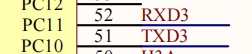
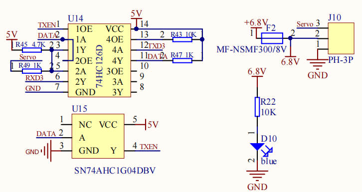
image-20220311103414861

image-20220311103037711

  1. Set serial port 3 to Asynchronous mode, and other parameters are shown in the figure below.
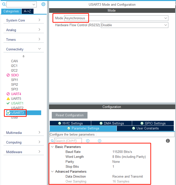
image-20220311104339865

  1. Since the default serial port 3 pins are PB10 and PB11, and the serial port 3 of the expansion board schematic diagram is connected to PC10 and PC11, the serial port remapping function is required.

Click the PC11 pin first, and then select USART3_RX. After this operation, the pins of serial port 3 will be remapped to PC10 and PC11.
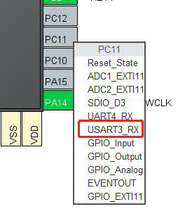
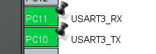
image-20220311105119846

image-20220311105155048

10.3. Analysis of the experimental flow chart
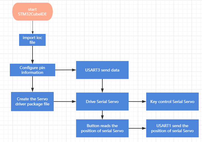
image-20220519103326496

10.4. core code explanation

  1. Create new bsp_uart_servo.h and bsp_uart_servo.c, and add the following content in bsp_uart_servo.h:
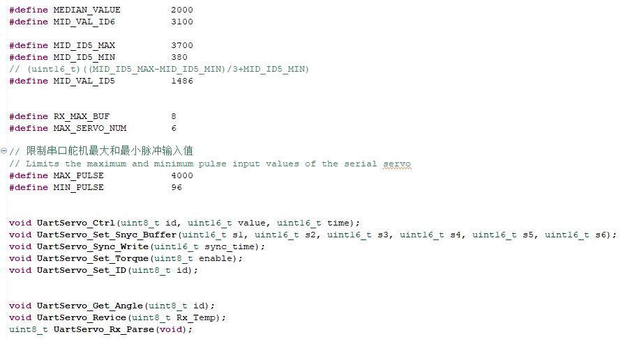
image-20220311112552218

  1. Create the following content in the bsp_uart_servo.c file:

According to the communication protocol of the serial servo, create a new UartServo_Ctrl(id, value, time) to control the servo. The id corresponds to the ID of the servo to be controlled. If id=0xFE(254), all servos will be controlled. value indicates the position to which the control servo moves, time indicates the running time, before reaching the maximum speed, the shorter the time, the faster the running.
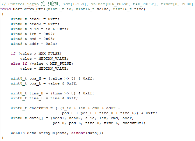
image-20220311114241465

  1. The UartServo_Get_Angle() function requests the current position of the servo.
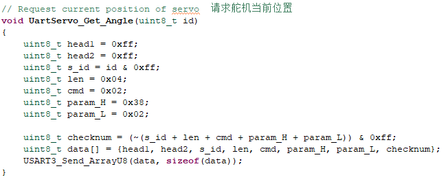
image-20220311115303590

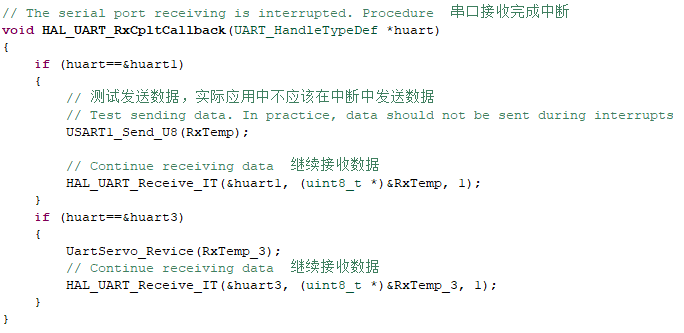
  1. The UartServo_Revice(Rx_Temp) function receives the serial port 3 data to determine whether it conforms to the serial port servo communication protocol. If it conforms to a frame of data, update the Rx_Data array and set New_Frame to 1.
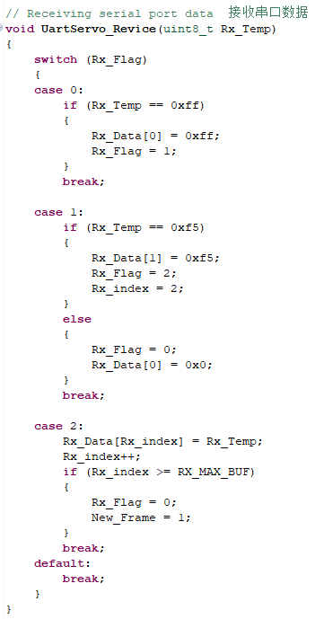
image-20220311115356697

  1. Parse the data returned by the serial port servo, return 1 if the read is successful, and print the data, otherwise return 0.
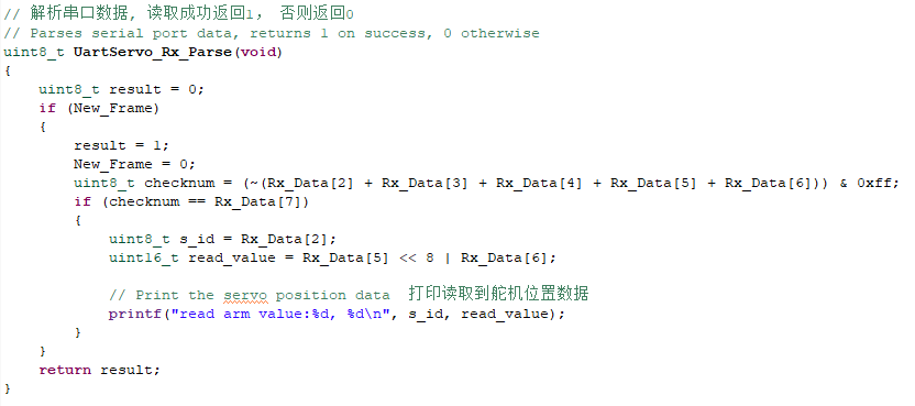
image-20220311115653298

  1. Add the following functions related to writing and reading of serial port 3 in bsp_uart.c.
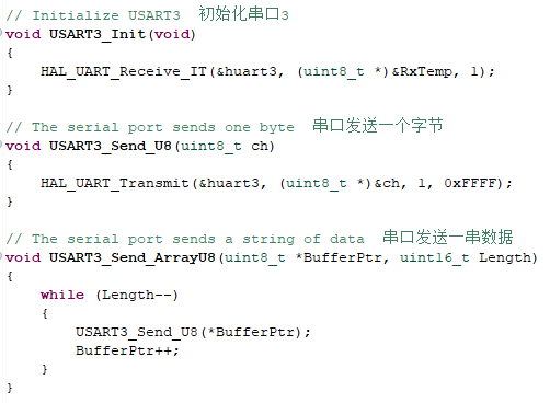
image-20220311120541249

image-20220311120634343

  1. Add the content of serial port 3 initialization in the Bsp_Init() function.
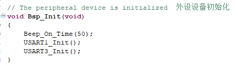
image-20220311120708777

  1. In the Bsp_Loop() function, add the function of key reading and controlling the serial port servo.
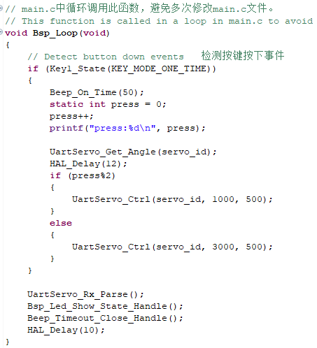
image-20220311120826504

10.5. Hardware connection

The serial port servo needs to be connected to the serial port servo port on the expansion board. The serial port servo port has the function of preventing reverse connection, and it can be inserted in the direction. Multiple serial servos can be cascaded. Due to the limited power supply current of the expansion board, do not connect too many servos. At present, six servos can be used normally.
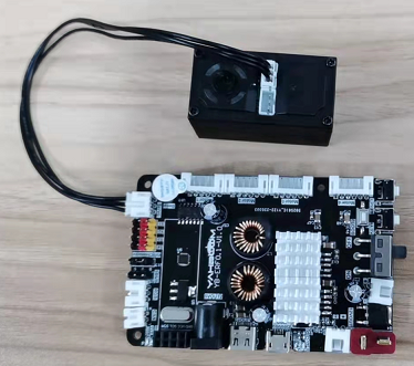
image-20220311121635417

Because the power of the serial port servo is relatively large, the expansion board should not be powered by USB 5V directly, it needs to be powered by DC 12V.

10.6. Experimental effect

After the program is programmed, the LED light flashes every 200 milliseconds. Press the button multiple times, the serial servo will go back and forth between the 1000 position and the 3000 position, and return to the position data before the movement.

Timer Interrupt to Control PWM Servo
Nine-axis Attitude Sensor to Obtain Data

COMPANY

  • About us
  • Team Style
  • Blog

LEARNING & EXPLORATION

  • Tutorials
  • Edge AI hardware
  • Educational robots
  • Embedded intelligent hardware

WHERE TO BUY

  • Yahboom Online Store
  • Amazon
  • Alibaba
  • AliExpress
  • Mercado

TECHNOLOGY SUPPORT

  • Email: support@yahboom.com

BE A DISTRIBUTOR

  • Email: sales@yahboom.com
QR Code

Copyright © 2017-2026 Yahboom. All Rights Reserved.

EN/中文