Welcome to ROSMASTER A1 PRO repository
3.OpenClaw Arm Fixed-point Placement
OpenClaw Robotic Arm Fixed-point Placement
OpenClaw Robotic Arm Fixed-point Placement1. Course ContentCourse OverviewLearning Objectives2. Preparation3. Robotic Arm Fixed-point Placement Case PracticeStep 1: Issue Placement CommandStep 2: Generate Grid Image and Point VerificationStep 3: Smooth Placement and Safe Retreat4. Core Source Code Analysis4.1 GetPlacePoint() — Semantic Spatial Point and Workspace Verification4.2 place() and _place() — Inverse Kinematics Solving and Smooth Release5. Parameter DebuggingKey Parameter Tuning Description Table6. Common Function Q&A and Advanced Tips6.1 What if the target point is too far and outside the robotic arm's working range?6.2 How to systematically troubleshoot when placement point is inaccurate?
1. Course Content
Course Overview
In the previous lesson, the robot learned how to "pick up" objects, and in the embodied intelligence closed loop, equally critical is "placing objects accurately".
In daily life and industrial sorting, we rarely throw objects randomly, but often with explicit spatial semantic instructions:
"Place the yellow block you just picked up in the middle of the red and blue blocks." "Put the toolbox in the empty space at the top-right corner of the table."
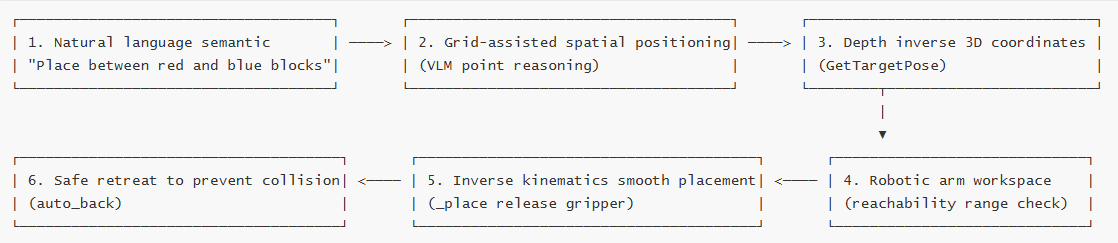
This is Semantic Precision Placement. There are three technical cores to achieve this task:
Understanding spatial relationships (semantic perception): The multimodal large model (VLM) needs to understand natural language spatial descriptions like "middle", "left side", "empty space", and find the most suitable target point in the camera view.
Calculating spatial coordinates (3D back-projection): The target pixel point on the 2D image is inversely solved through RGB-D depth to obtain the robot's 3D spatial coordinates (X, Y, Z).
Reachability and inverse kinematics solution (IK solving): Check if the point is within the robotic arm's maximum reach; if within range, calculate each joint angle to safely deliver the block and gently release the gripper.
Note
Hardware note: This lesson's visual semantic adaptive placement function relies on depth camera's 3D point cloud ranging; if using the monocular USB camera version, the system will use fixed preset point placement.
Learning Objectives
Master the method of controlling the robotic arm for semantic fixed-point placement through natural language dialogue with OpenClaw.
Understand the principle of image overlay grid (Grid Overlay) assisting the large model for precise positioning.
Learn to use
GetPlacePointto obtain 3D coordinates of placement point and verify robotic arm workspace.Master the tuning technique for placement offset
place_offsetto achieve smooth landing.
2. Preparation
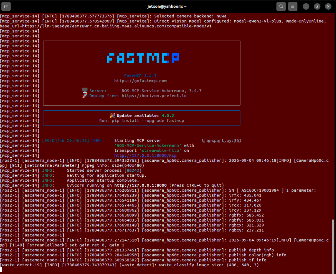
Start core nodes such as odometry, TF transformation, robotic arm assistance, camera node, and MCP service:
ros2 launch dofbot_pro_bringup mcp_service.launch.pyIf you need voice replies, you can use the command with the
launch_openclaw_bridgeparameter, otherwise you can simply use the basic command above:
xxxxxxxxxxros2 launch dofbot_pro_bringup mcp_service.launch.py launch_openclaw_bridge:=true
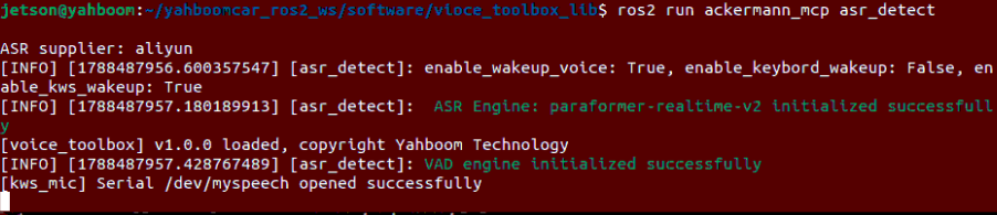
If you need voice dialogue interaction, you can run the following command (choose either the WebChat web interface or voice wake-up interaction):
xxxxxxxxxxros2 run ackermann_mcp asr_detect
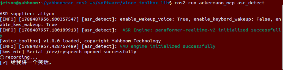
After shouting the wake-up word Hi,yahboom, the indicator light turns on, and you can then speak the content you want to discuss:
3. Robotic Arm Fixed-point Placement Case Practice
Tip
Instructions can be expressed naturally according to your actual needs. Here is a case demonstration; you can choose either interaction method. This example uses the WebChat web interface.
Under the hood, OpenClaw translates human language and calls the following two core tools:
| Tool Name | Input Parameters | Core Function |
|---|---|---|
GetPlacePoint | --query (natural language description) | Analyze coordinates of points in the image matching the description, and check if within robotic arm workspace |
Place | --place-x, --place-y, --place-z | Control robotic arm to precisely and smoothly place the held object at specified 3D coordinates |
Step 1: Issue Placement Command
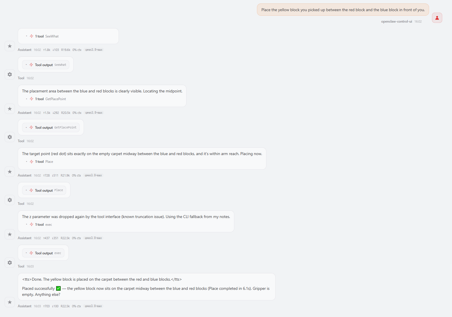
With the robotic arm already gripping the yellow cube, enter the placement command in the WebChat interface, for example:
"Place the yellow block you picked up between the red block and the blue block in front of you."
Step 2: Generate Grid Image and Point Verification
When calling the GetPlacePoint tool, the system automatically captures the current view in the background and draws fine grid lines on the image for the multimodal model to position.
Then, the program automatically generates and saves a point verification image for developers to intuitively observe whether the placement point determined by the large model is accurate:
xxxxxxxxxx~/MODELS/multi_brains_file/place_verify_image.png
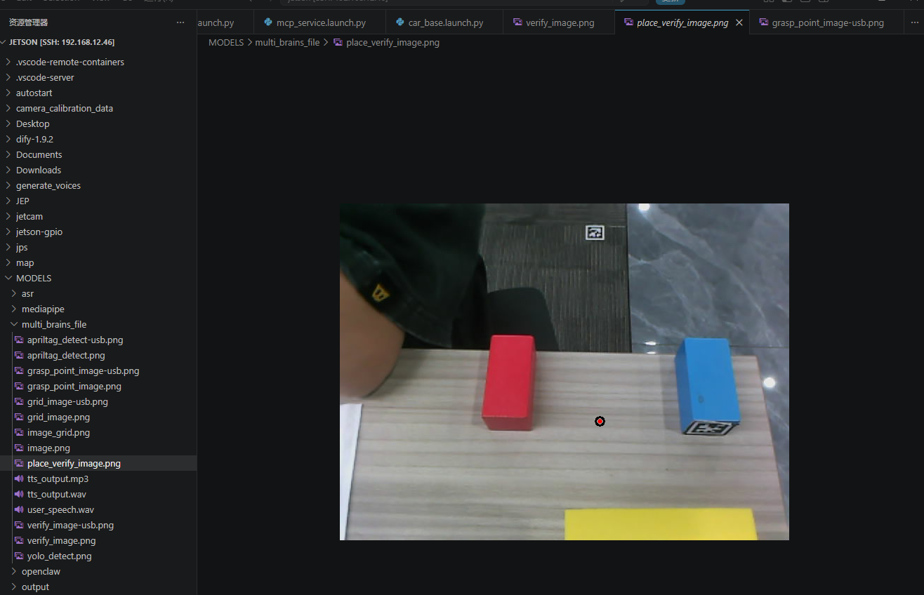
Image annotation description:
Black circle: Valid area for sampling surrounding point cloud (
target_circleradius).Center red point: The precise placement center calculated by the large model. If the red point falls exactly on the empty desk space between the red and blue blocks, the visual reasoning is completely as expected!
Step 3: Smooth Placement and Safe Retreat
The USB camera version does not have this step
After confirming the target point is within the robotic arm's reachable range, OpenClaw calls the Place tool. The robotic arm smoothly delivers the yellow cube to the target above, descends slowly, releases the gripper, and finally the car chassis automatically backs up a safe distance (auto_back_dist) to avoid the robotic arm colliding with the just-placed cube when lifting up.
4. Core Source Code Analysis
Source code file path:
xxxxxxxxxx~/yahboomcar_ros2_ws/dofbot_pro_ws/src/ackermann_mcp/ackermann_mcp/action_controller.py
Fixed-point placement consists of two core interfaces: GetPlacePoint() responsible for visual spatial understanding and place() (and underlying action _place()) responsible for robotic arm motion execution.
4.1 GetPlacePoint() — Semantic Spatial Point and Workspace Verification
xxxxxxxxxxdef GetPlacePoint(self, query: str) -> list[bool, str]: """Get 3D spatial coordinates of placement point based on natural language semantics""" # Step 1: Capture current camera view save_result = self.SeeWhat() if not save_result[0]: return [False, f"SeeWhat error:{save_result[1]}", ""] # Step 2: Overlay 20px grid reference lines on image to assist visual Agent positioning img = draw_grid_overlay(image=cv2.imread(self.image_path), grid_size=20) cv2.imwrite(self.grid_images_path, img) agent_result = self._request_dify_agent(query, self.grid_images_path, TYPE="POINT") if not agent_result[0]: return [False, f"Dify Agent error:{agent_result[1]}", ""] # Step 3: Parse pixel coordinates, check if target point exists point_data = agent_result[1].get("point", {}) x, y = point_data.get("x"), point_data.get("y") if x == -1 and y == -1: return [False, "Target point does not exist in the image", ""] # Step 4: Draw visualized point verification image img = cv2.imread(self.image_path) cv2.circle(img, (x, y), self.target_circle, (0, 0, 0), 2) # Black sampling circle cv2.circle(img, (x, y), 3, (0, 0, 255), -1) # Red center point cv2.imwrite(self.place_verify_image_path, img) # Step 5: Call 3D pose service, back-project to get 3D coordinates in robotic arm coordinate system (X, Y, Z) request = GetTargetPose.Request(x=float(x), y=float(y), radius=self.target_circle) result = self.get_pose_client.call(request) if not result.success: return [False, str(result.message), ""] point = str({"x": round(result.pose.position.x, 2), "y": round(result.pose.position.y, 2), "z": round(result.pose.position.z, 2)}) # Step 6: Robotic arm physical workspace reachability safety check if result.pose.position.x <= self.place_distance[2] and \ result.pose.position.y <= self.place_distance[3]: msg = "✅ Target point is within working range" else: msg = "❌ Target point is outside working range" return [True, msg, point]4.2 place() and _place() — Inverse Kinematics Solving and Smooth Release
xdef place(self, place_x: float, place_y: float, place_z: float) -> list[bool, str]: """Main entry for robotic arm object placement""" # 1. Call underlying inverse kinematics action method, pass in 3D coordinates and preset pitch angle self._place(place_x, place_y, place_z, place_pitch=self.place_offset[3])
# 2. Auto retreat after placement to free up safe space self.move_by_odom(direction='backward', distance=self.auto_back_dist) self.get_logger().info("Place object complete") return [True, ""]Underlying execution function _place():
xxxxxxxxxxdef _place(self, place_x, place_y, place_z,            place_roll=0.0, place_pitch=0.0, place_yaw=0.0):    # Step 1: Superimpose placement fine-tuning offset, construct inverse kinematics solving request    request = ArmKinemarics.Request()    request.tar_x = place_x + self.place_offset[0]    request.tar_y = -(place_y + self.place_offset[1])  # Y-axis negated (coordinate system conversion convention)    request.tar_z = place_z + self.place_offset[2]    request.kin_name = "ik"    request.roll = place_roll    request.pitch = place_pitch    request.yaw = place_yaw
    # Step 2: Request robotic arm kinematics server to calculate target angles for 6 joints    response: ArmKinemarics.Response = self.arm_kin_client.call(request)    self.get_logger().info(f"place IK-pose: {response}")
    # Step 3: Drive 6 joints of robotic arm to smoothly move to target placement posture    joints = [int(response.joint1), int(response.joint2), int(response.joint3),              int(response.joint4), int(response.joint5), self.GraspKeepPose[5]]    self._pubSix_Arm(joints)    time.sleep(4.0)  # Give sufficient time for robotic arm to smoothly reach position, prevent shaking        # Step 4: Control gripper motor to open (joint 6 angle returns to 0), gently release object    self.SingleJoint_pub.publish(ArmJoint(id=6, joint=0, time=1500))    time.sleep(2.0)  # Wait for block to steadily land        # Step 5: Retract and reset robotic arm, restore initial default safe posture    self._pubSix_Arm(self.init_arm_pose)
5. Parameter Debugging
Core parameter configuration file path:
xxxxxxxxxx~/yahboomcar_ros2_ws/dofbot_pro_ws/src/dofbot_pro_bringup/config/common.yaml
Parameters related to placement function:
xxxxxxxxxxmcp_service ros__parameters # Robotic arm placement and reachability parameters place_distance0.39 0.0 0.45 0.25 # [X base, Y base, X max working limit, Y max working limit] place_offset-0.01 0.00 0.05 1.3 # Depth camera placement fine-tuning [X offset, Y offset, Z height micro-lift, pitch angle] putdown_joints90 -10 58 78 89 140 # USB camera fixed placement posture (6 joint angles, unit: degrees) auto_back_dist0.13 # Auto retreat distance after placement (meters) target_circle10 # Spatial point sampling area radius (pixels)Key Parameter Tuning Description Table
| Parameter Name | Default Value | Function and Physical Meaning | Adjustment Suggestion |
|---|---|---|---|
place_distance[2] | 0.45 | Maximum allowed forward reach distance of robotic arm X-axis (meters) | Set according to robotic arm reach, too large may cause IK solving failure |
place_distance[3] | 0.25 | Maximum allowed lateral span of robotic arm Y-axis (meters) | Prevent arm from extending too far sideways causing insufficient torque |
place_offset[0] | -0.01 | Front-rear direction fine-tuning of placement point (meters) | If placing too far forward, set to negative value to micro-retract |
place_offset[1] | 0.00 | Left-right direction fine-tuning of placement point (meters) | Follow right-hand coordinate system, compensate left, compensate right negatively |
place_offset[2] | 0.05 | Lifting height during placement (meters) | Recommend keeping 0.03~0.06, both prevents hitting table and ensures accurate placement |
place_offset[3] | 1.3 | Pitch angle during placement (Pitch, radians) | Approximately equals downward tilt of 75°, keep gripper vertical for material dropping |
putdown_joints | [90, -10, 58, 78, 89, 140] | USB camera exclusive fixed placement 6 joint angles | Fine-tune USB fixed placement point: Want to place more left: Increase joint 1 (e.g., adjust to 100°~120°) Want to place more right: Decrease joint 1 (e.g., adjust to 80°~60°) Want to place lower/higher: Fine-tune joint 3 and joint 4 angles (recommend ±3°~5° each time) |
6. Common Function Q&A and Advanced Tips
6.1 What if the target point is too far and outside the robotic arm's working range?
If the large model identifies the target placement point as too far from the car body, exceeding the place_distance limit, OpenClaw can call the chassis pose matching tool AdjustChassisFitArmRange to first drive the car to the target:
xxxxxxxxxx# Source code location: AdjustChassisFitArmRange()def AdjustChassisFitArmRange(self, x: float, y: float, z: float) -> bool: delta_x = x - self.place_distance[0] # Calculate front-rear direction distance difference delta_y = y - self.place_distance[1] # Calculate left-right direction lateral deviation # Front-rear approach movement self.move_by_odom(distance=abs(delta_x), direction='forward') # Left-right alignment movement direction = 'left' if delta_y > 0 else 'right' self.move_by_odom(distance=abs(delta_y), direction=direction) return TrueAfter the car moves to compensate for the distance difference, the target point re-enters the robotic arm's reachable range, and then executing place can smoothly complete the placement.
6.2 How to systematically troubleshoot when placement point is inaccurate?
Please follow this two-step troubleshooting approach:
First check eyes (visual point): Open
~/MODELS/multi_brains_file/place_verify_image.png.If the red point is not circled at the target position (e.g., VLM misjudged due to too dark lighting), it's a visual Prompt understanding deviation. Describe the reference more specifically in dialogue (e.g., "place it about 5cm to the right of the green cube").
Then check hand (mechanical pose): If the red point on the image is very accurate but the robotic arm still has slight deviation when releasing.
This is a robotic arm zero-point minor calibration tolerance. Simply modify the
place_offsetoffset incommon.yamlfor millimeter-level compensation.