Welcome to ROSMASTER A1 PRO repository
0.Robotic Arm Basic Usage
🦾 Robotic Arm Basic Usage and Driver Control Tutorial
1. Course Overview
Before diving into advanced applications like 3D vision grasping, object sorting, and MoveIt2 autonomous obstacle avoidance, mastering the robotic arm's low-level driver node startup, control topics and service invocation methods, as well as fundamental concepts of spatial coordinate systems, is an essential lesson for every robotics developer.
This course is based on the ROS 2 robotics system and covers:
Starting the Low-Level Hardware Driver: Run
A1pro_camera_arm.launch.pyto start serial communication, camera driver, and kinematics service;Robotic Arm Control Topics:
Publish to
/arm6_jointstopic for multi-joint coordinated control;Publish to
/arm_jointtopic for single joint/gripper independent control;Subscribe to
/arm_status/arm_jointtopic to read the robotic arm's real-time joint status;
Robotic Arm Service Calls:
Call
/arm_driver/set_torqueservice for one-touch torque release and recovery;Call
/arm_driver/get_actual_arm_positionservice to read back servo physical angles;Call
/get_kinemaricsservice for forward and inverse kinematics computation;
Pose Monitor and Drag Teaching Tool (
arm_pose_monitor): Quick calibration and waypoint recording;ROS Robot Spatial Coordinate System and Pose Fundamentals: Right-hand rule, base frame, end-effector TCP, and camera optical axis.
2. Starting the Low-Level Hardware Driver
Before controlling the robotic arm, you must first start the integrated driver for the robot chassis, robotic arm servo communication, and camera.
Open a terminal and run:
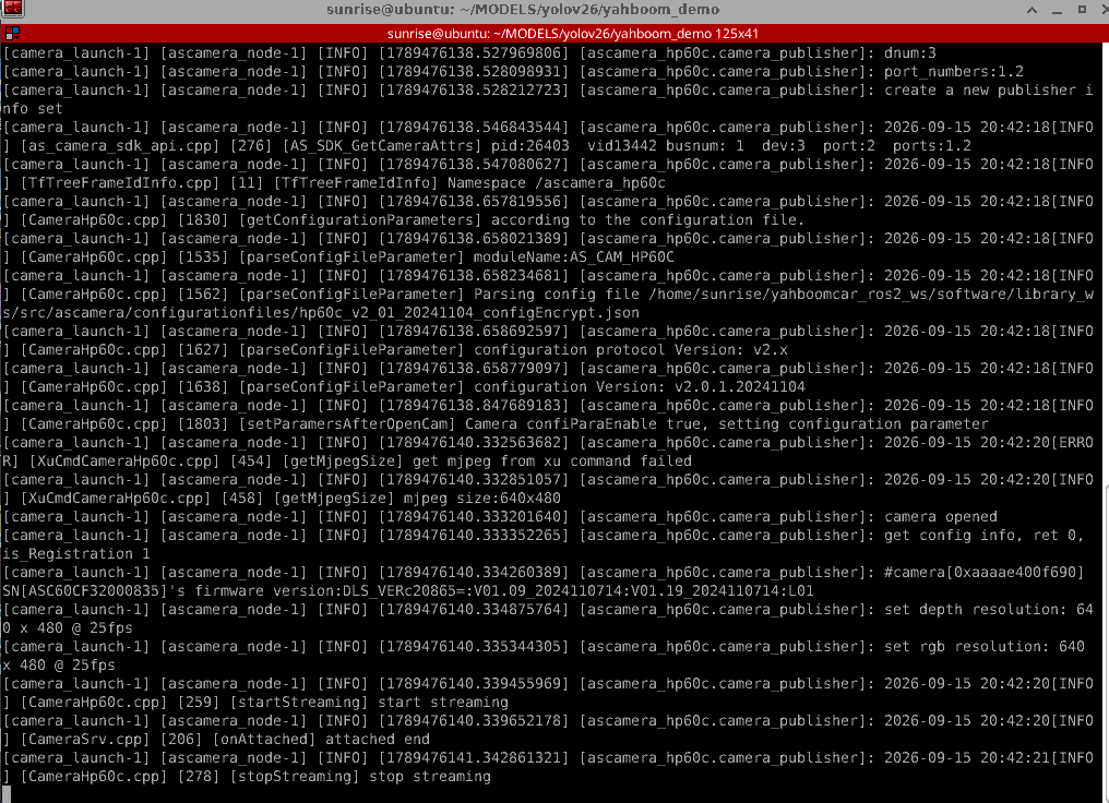
ros2 launch dofbot_pro_driver A1pro_camera_arm.launch.pyInternal Operation Mechanism: After this launch file starts, it brings up the following three core nodes:
Ackman_driver_A1P(node name/driver_node): Responsible for serial communication between the chassis and robotic arm low-level microcontroller/servo driver board, exposing joint control topics and torque services;
kinemarics_dofbot(node name/kinemarics_arm): Loads the robotic arm URDF kinematics model, providing forward/inverse kinematics service/get_kinemarics;Camera Driver Node: Automatically starts the HP60C depth camera (or USB camera) publishing image and point cloud data.
After successful startup, the terminal will remain in a listening state. Keep this terminal running; subsequent operations will be performed in new terminals.
3. Controlling the Robotic Arm via ROS 2 Topics
Open a new terminal. We can drive the robotic arm by publishing ROS topics via command line:
3.1 Multi-Joint Coordinated Motion Control (/arm6_joints)
Topic Name:
/arm6_jointsMessage Type:
dofbot_pro_interface/msg/ArmJointsField Definitions:
joints: A float array of length 6, corresponding to the target angles for servo 1 through 5 (arm body) and servo 6 (gripper);run_time: Motion time (unit: milliseconds), controlling how long the robotic arm takes to smoothly transition from current pose to target pose.
Example 1: Control the robotic arm to return to initial upright/centered pose (1500ms)
xxxxxxxxxxros2 topic pub --once /arm6_joints dofbot_pro_interface/msg/ArmJoints "{joint1: 90, joint2: 90, joint3: 90, joint4: 90, joint5: 90, joint6: 30, time: 1500}"Example 2: Control the robotic arm to lean forward in preparation for grasping
xxxxxxxxxxros2 topic pub --once /arm6_joints dofbot_pro_interface/msg/ArmJoints "{joint1: 90, joint2: 120, joint3: 0, joint4: 0, joint5: 90, joint6: 30, time: 1000}"3.2 Single Joint/Gripper Independent Control (/arm_joint)
If you only need to fine-tune a single joint, or open/close the gripper separately, use the single joint topic:
Topic Name:
/arm_jointMessage Type:
dofbot_pro_interface/msg/ArmJointField Definitions:
id: Servo ID;angle: Target angle;run_time: Running time (ms).
Example 1: Open the gripper (servo 6 rotates to 0°)
xxxxxxxxxxros2 topic pub --once /arm_joint dofbot_pro_interface/msg/ArmJoint "{id: 6, joint: 0, time: 800}"Example 2: Close the gripper (servo 6 rotates to 90°)
xxxxxxxxxxros2 topic pub --once /arm_joint dofbot_pro_interface/msg/ArmJoint "{id: 6, joint: 90, time: 800}"Example 3: Control servo 1 (base) to rotate horizontally left to 135°
xxxxxxxxxxros2 topic pub --once /arm_joint dofbot_pro_interface/msg/ArmJoint "{id: 1, joint: 135, time: 1000}"3.3 Real-Time Monitoring of Robotic Arm Joint Status (/arm_status/arm_joint)
The low-level driver board continuously reads back the actual servo angles at approximately 5Hz and converts them to standard ROS joint state messages:
Topic Name:
/arm_status/arm_jointMessage Type:
sensor_msgs/msg/JointState
Enter the following command in the terminal to print the current joint radians and joint names in real time:
xxxxxxxxxxros2 topic echo /arm_status/arm_joint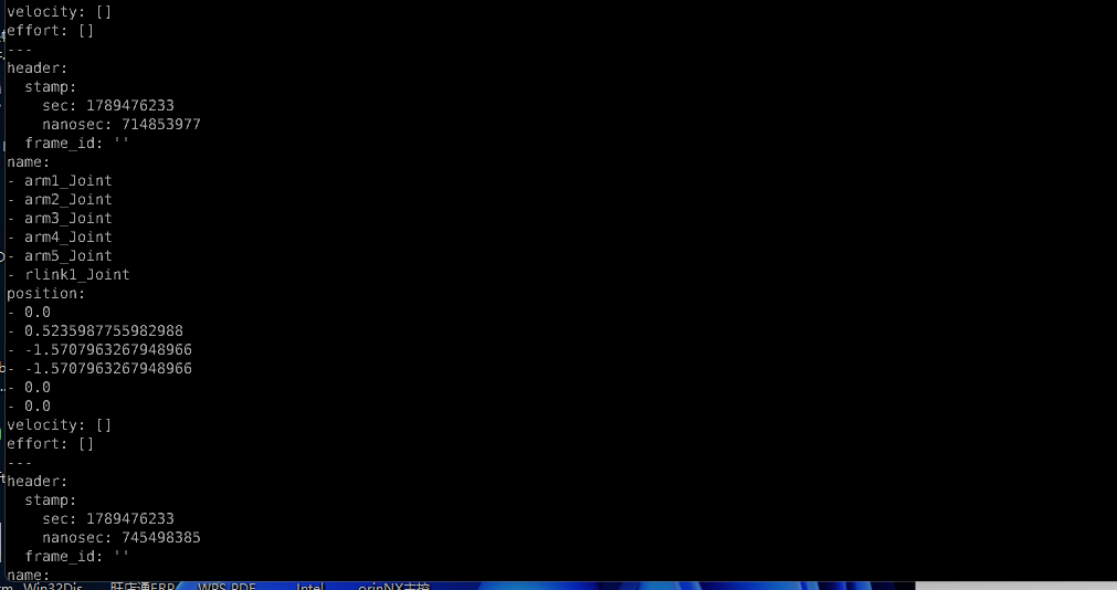
4. Controlling the Robotic Arm via ROS 2 Services
In addition to topic communication, the system also provides rich services supporting request-response mode precise interaction:
4.1 Servo Torque Switching Service (/arm_driver/set_torque)
During robotic arm debugging or manual teaching, we often need to "power down" the servos so they can be easily moved by hand; after teaching is complete, restore power and lock them.
Service Name:
/arm_driver/set_torqueService Type:
std_srvs/srv/SetBoolField Description:
data: falsereleases torque (power down),data: truerestores power and locks.
Example 1: Release torque on robotic arm (power down, can be manually dragged)
⚠ Warning: Before executing the torque release command, be sure to support the robotic arm with your hand to prevent it from rapidly falling and hitting the table due to gravity!
xxxxxxxxxxros2 service call /arm_driver/set_torque std_srvs/srv/SetBool "{data: false}"Example 2: Restore power and lock the robotic arm
xxxxxxxxxxros2 service call /arm_driver/set_torque std_srvs/srv/SetBool "{data: true}"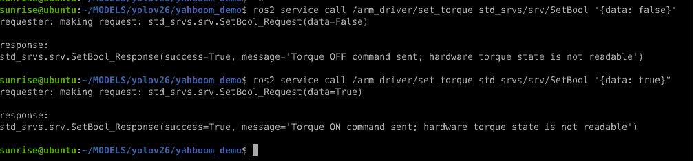
4.2 Read Back Servo Actual Physical Angle Service (/arm_driver/get_actual_arm_position)
Service Name:
/arm_driver/get_actual_arm_positionService Type:
dofbot_pro_interface/srv/ArmPosition
After sending a request, the low-level driver board queries each of the 6 bus servos once for their actual angles and returns a float array:
xxxxxxxxxxros2 service call /arm_driver/get_actual_arm_position dofbot_pro_interface/srv/ArmPosition "{}"Terminal response example:

4.3 Kinematics Forward and Inverse Computation Service (/get_kinemarics)
Service Name:
/get_kinemaricsService Type:
arm_interface/srv/ArmKinemarics
Forward Kinematics (FK Mode): Input servo angles to calculate end-effector 3D spatial coordinates
xxxxxxxxxxros2 service call /get_kinemarics arm_interface/srv/ArmKinemarics "{kin_name: 'fk', cur_joint1: 90.0, cur_joint2: 90.0, cur_joint3: 90.0, cur_joint4: 90.0, cur_joint5: 90.0}"The terminal will output the end-effector's [X, Y, Z] coordinates (unit: meters) and [Roll, Pitch, Yaw] orientation angles (unit: radians) relative to the base frame.
Inverse Kinematics (IK Mode): Input target spatial coordinates to calculate target angles for servos 1-5
xxxxxxxxxxros2 service call /get_kinemarics arm_interface/srv/ArmKinemarics "{kin_name: 'ik', tar_x: -0.002661, tar_y: 0.0002654, tar_z: 0.5263, roll: 0.0, pitch: 0.0, yaw: 0.0}"The terminal will output the joint1 ~ joint5 target servo angles required for the robotic arm end-effector to reach that position.
5. Pose Monitor and Drag Teaching Tool
To avoid manually calling services to check angles every time, the system provides a visual terminal pose monitoring tool arm_pose_monitor:
5.1 Starting the Monitor
With the low-level driver running, open a new terminal and run:
xxxxxxxxxxros2 run movelt_demo arm_pose_monitorThe terminal will display a clean real-time dashboard:
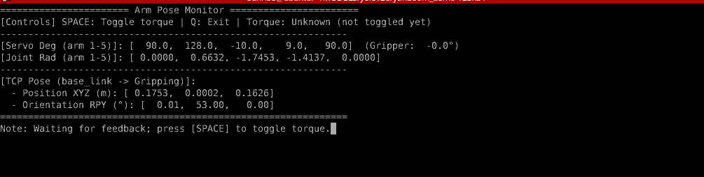
5.2 Three-Step Method for Drag Teaching Point Collection
Lightly press spacebar (release torque): Support the robotic arm with your hand, press the [Spacebar], servos release torque;
Manually move the robotic arm to the target position: Move the robotic arm to the grasping or placement point by hand, observe the dashboard values changing in real time. To use later, simply select and copy the 5 values inside brackets after
[Servo Deg (arm 1-5)];Restore locking and exit: Press [Spacebar] again to restore power and lock, press [Q] to exit the monitor.
6. ROS Robot Coordinate System and Pose Fundamentals
When writing upper-level automation planning and vision algorithms, you must understand the geometric topological relationships between the robot's various coordinate frames:
6.1 Right-Hand Rule
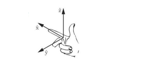
All coordinate systems in ROS 2 strictly follow the Cartesian right-hand coordinate system:
Coordinate Axis Direction Rules:
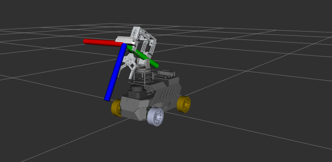
Extend your right hand, thumb pointing forward is the positive X axis;
Index finger pointing left is the positive Y axis;
Middle finger perpendicular to palm pointing up is the positive Z axis;
Mnemonic (RGB ↔ XYZ): When observing coordinate frames in RViz, Red axis represents X, Green axis represents Y, Blue axis represents Z.
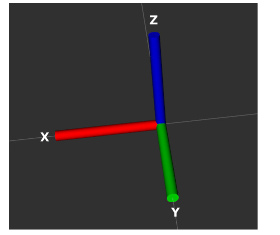
Positive Rotation Direction (Right-Hand Screw Rule):
Point your right thumb in the positive direction of an axis; the natural curling direction of your fingers when making a fist indicates the positive angle direction of rotation around that axis;
Rotation around X axis is called Roll;
Rotation around Y axis is called Pitch;
Rotation around Z axis is called Yaw.
6.2 Key Reference Base Coordinate Frames
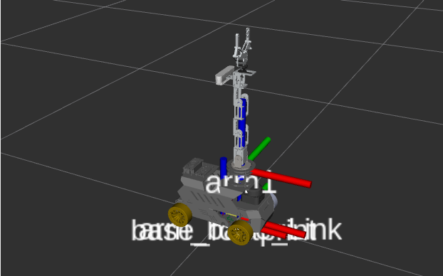
base_footprint: The contact point center of the chassis on the ground projection, approximately 2cm above arm_base_link, the global reference frame for vehicle navigation and localization;arm_base_link: The geometric center of the chassis body, located on the vehicle chassis frame. MoveIt robotic arm motion planning and collision detection use this as the default reference;arm1/ Robotic Arm Base: The starting joint coordinate frame for the robotic arm mounted at the front of the vehicle.
6.3 Robotic Arm End-Effector Working Center (TCP - Tool Center Point)
GrippingCoordinate Frame: Defined at the geometric center point of contact when the dual-finger parallel gripper closes (Tool Center Point / TCP);Spatial motion planning and obstacle avoidance—what is referred to as "the end-effector reaching a certain coordinate"—is essentially moving the
Grippingworking center to the desired 3D spatial position.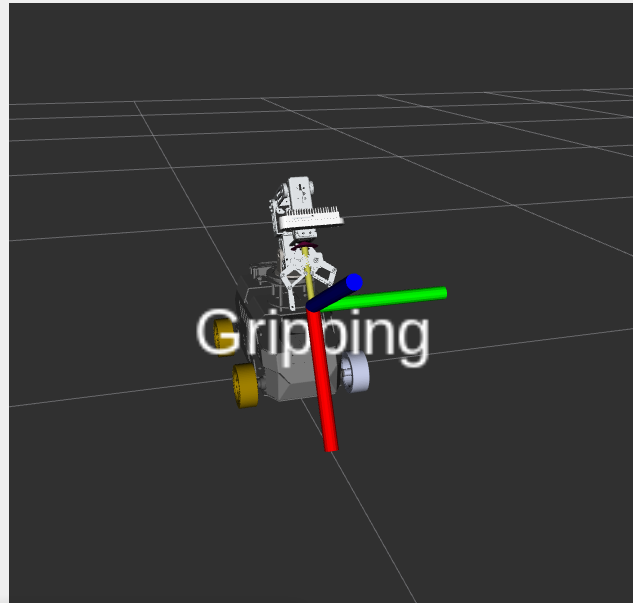
6.4 Camera Optical Axis Coordinate Frame and TF Space Alignment
Camera Optical Coordinate Frame: The optical coordinate frame of depth cameras (like HP60C) follows image processing conventions:
Z axis points forward (along the lens optical axis outward, perpendicular into the measured object's distance direction);
X axis points right (corresponding to horizontal image pixel column direction);
Y axis points down (corresponding to vertical image pixel row direction);
Static TF Rigid Transform: At system startup, a static TF publishing node aligns the camera optical axis coordinate frame to the robot's
base_link, ensuring that objects or 3D point clouds identified by the camera can be accurately projected into the robotic arm's graspable spatial coordinates.
6.5 Spatial End-Effector Pose Control and Underactuated (5-DOF) Explanation
Fully positioning the robotic arm end-effector in space requires 6 degrees of freedom (3 position + 3 orientation), but A1Pro only has 5 joints, making it an underactuated configuration that cannot precisely control all 6 quantities simultaneously. Therefore, a position-priority strategy is adopted in actual planning: prioritize ensuring the end-effector gripper reaches the target position (X,Y,Z), with the orientation automatically solved by the inverse solver, significantly improving grasping and obstacle avoidance success rates.