Welcome to ROSMASTER A1 PRO repository
8.Color Block Tracking and Grasping
🎯 Visual Tracking and Grasping Dynamic Color Blocks
1. Course Overview
The function implemented in this lesson can be simply understood as: robotic arm "eyes" fixate on the specified color block, automatically follow movement, and approach to grasp when aligned.
By extracting the target block's centroid in the HSV color space, using PID closed-loop control of the robotic arm's joint 1 base servo and joints 2/3/4 pitching, the camera always faces the block directly. After the block centroid is continuously stable in the image center, the chassis automatically advances to the grasping distance (approximately 230~240mm), and the robotic arm executes IK descent to complete grasping.
Note
The tutorial recommends using the accompanying 4×4cm colored wooden blocks. The larger size helps improve tracking stability.
2. Preparation and Running
This case requires opening 3 terminals to start the system sequentially:
2.1 Start Camera Driver and Kinematics Solver Environment
Run in Terminal 1:
ros2 launch dofbot_pro_driver A1pro_camera_arm.launch.py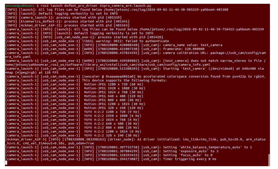
2.2 Start Robotic Arm Desktop Grasping Action Execution Node
Run in Terminal 2:
x# Depth camera version (Nuwa)ros2 run dofbot_pro_driver grasp_desktop
# Or USB camera versionros2 run dofbot_pro_usb grasp_usb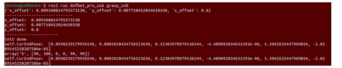
2.3 Start Color Block Tracking Node
Run in Terminal 3:
xxxxxxxxxx# Depth camera version (Nuwa)ros2 run dofbot_pro_driver color_follow_2D
# Or USB camera versionros2 run dofbot_pro_usb color_follow_usb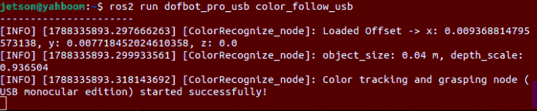
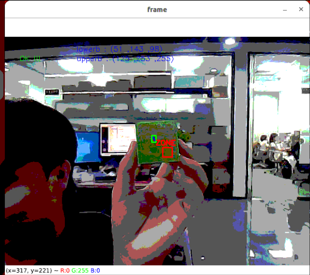
Mouse click to select color:
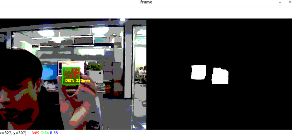
3. Operation Demo and Interaction Flow
Select Target Color:
With the image window active, press the C key to enter color selection mode;
Use the mouse to drag and select the block. Resample HSV thresholds under the current lighting environment and automatically save to
custom_colorHSV.text. The system immediately locks onto that color target and enters servo tracking;
Handheld Material Guidance Tracking:
Hold the 4×4cm block and slowly move it within the field of view in front of the robotic arm;
The robotic arm will automatically perform gimbal PID servo rotation based on the block centroid offset, keeping the camera crosshair aligned with the block;
Center Locking and Chassis Approach:
After the block centroid stably enters the center target box, the gimbal pose locks, and the chassis automatically and smoothly drives forward toward the block;
Automatic Grasping Trigger:
After reaching optimal grasping distance, chassis stops, buzzer sounds, robotic arm automatically computes the gripper alignment angle and descends to grasp;
After grasping, the robotic arm lifts the material and resets, resetting status flags to prepare for the next tracking cycle.
Tip
When moving the block, please move slowly and smoothly. Too fast movement can cause motion blur in the image and lead to PID tracking overshoot.
4. Core Source Code Analysis
The system is completed by "color block tracking decision" and "IK execution" two nodes working in coordination:
| Camera Type | Color Block Tracking Decision Node | Grasping Action Execution Node |
|---|---|---|
| USB Monocular Camera | dofbot_pro_usb/color_follow_usb.py | dofbot_pro_usb/grasp_usb.py |
| 3D Depth Camera | dofbot_pro_driver/color_follow_2D.py | dofbot_pro_driver/grasp_desktop.py |
Regardless of which camera is mounted, the program underlying is designed as a four-stage state machine:
xxxxxxxxxxPhase A: Gimbal PID Tracking -> Phase B: Continuous Center Locking -> Phase C: Chassis Active Approach -> Phase D: Gripper Adaptive Grasping
The main technical implementation comparison between the two:
| Comparison Dimension | USB Monocular Camera Solution | 3D Depth Camera Solution (Nuwa-HP60C) |
|---|---|---|
| Alignment Center Reference | Image optical center TARGET_X = 341, TARGET_Y = 242 | Image standard center TARGET_X = 320, TARGET_Y = 240 |
| Lock Transition Mechanism | Switch to approach immediately when block centroid enters center tolerance box | Continuous 10 frames lock (ALIGN_COUNT_THRESHOLD = 10) before confirming approach, stronger anti-noise capability |
| Ranging and Grasping Distance | Pinhole calculated distance, approach to approximately 230mm | Depth map matrix directly reads true millimeter depth, approach to approximately 240mm |
| Spatial Compensation Dimension | Superimpose X, Y 2D spatial calibration deviation | Synchronously superimpose X, Y, Z 3D omnidirectional compensation from offset_value.yaml |
4.1 USB Monocular Camera Core Source Code Analysis (color_follow_usb.py)
1. Gimbal PID Dynamic Following and Slope Limiting
Calculate pixel deviation between block centroid and target optical center, drive joints through PID with slope limiter (max_step_change = 0.03) to prevent jitter:
xxxxxxxxxx# color_follow_usb.py —— XY_track gimbal trackingraw_angular_x = self.angular_x_PID.compute(center_x, TARGET_X)raw_angular_y = self.angular_y_PID.compute(center_y, TARGET_Y)
# Slope limiter smoothing filterdiff_x = raw_angular_x - self.last_angular_xangular_x = self.last_angular_x + max(-self.max_step_change, min(self.max_step_change, diff_x))
target_j1 = 90  + (10 * angular_x * -90.0)   # Base rotationtarget_j2 = 150 + (angular_y * -150.0)        # Pitch coordinationtarget_j3 = 12  + (angular_y * -60.0)target_j4 = 20  + (angular_y * -100.0)
2. Chassis Approach and Descent Grasping
After centroid alignment and gimbal lock, chassis uses forward/backward PID to approach 230mm, combined with block bounding box corner vectors compute_joint5(vx, vy) to calculate gripper alignment angle and trigger grasping.
4.2 3D Depth Camera Core Source Code Analysis (color_follow_2D.py)
1. Depth Map Direct Extraction of True Distance
The depth camera subscribes to RGB and Depth through ApproximateTimeSynchronizer. After tracking the block centroid (center_x, center_y), it directly indexes the true physical distance from the depth map matrix and calculates the horizontal geometric distance between vehicle and block:
xxxxxxxxxx# color_follow_2D.py —— True physical depth reading and horizontal distance derivationcx_int = int(np.clip(center_x, 0, 639))cy_int = int(np.clip(center_y, 0, 479))
cur_depth = depth_image[cy_int, cx_int] / 1000.0  # Convert mm to meterspose_t = self.compute_heigh(center_x, center_y, cur_depth)self.cur_distance = math.sqrt(pose_t[1]**2 + pose_t[0]**2) * 1000.0  # millimeters
2. 10-Frame High-Robustness Locking Strategy
For block reflection or slight jitter, the depth camera version uses a stricter 10-frame continuous center alignment mechanism (ALIGN_COUNT_THRESHOLD = 10). After confirming target stability, buzzer sounds and smoothly advances to 240mm:
xxxxxxxxxx# color_follow_2D.py —— State machine transition controlif is_aligned and self.Done_flag and not self.adjust_dist and not self.start_grasp:    self.aligned_count += 1    if self.aligned_count >= ALIGN_COUNT_THRESHOLD:  # Continuous stable 10 frames        self.Beep_Loop()        self.adjust_dist = True                      # Enter approach phase        self.XY_Track_flag = False                   # Lock gimbal
if self.adjust_dist:    if self.cur_distance > GRASP_DIST + 0.2:        self.move_dist(self.cur_distance)    else:        if self.cur_distance > 200:            self.adjust_dist = False            self.start_grasp = True            self.pubVel(0, 0, 0)
3. Gripper Adaptive Angle Computation and 3D IK Grasping
After chassis stops, the algorithm calculates joint 5 target angle based on block contour vertex slope, sends target 3D coordinates and rotation angle to grasp_desktop, and after superimposing 3D compensation from offset_value.yaml, descends for precise grasping:
xxxxxxxxxx# color_follow_2D.py —— Gripper adaptive alignment and message publishingvx = int(self.corners[0][0]) - int(self.corners[1][0])vy = int(self.corners[0][1]) - int(self.corners[1][1])target_joint5 = compute_joint5(vx, vy)self.joint5.data = int(target_joint5)
self.TargetJoint5_pub.publish(self.joint5)self.pos_info_pub.publish(tag_msg)
Through this smooth adaptation of dual-camera solutions, whether using USB monocular lens or 3D depth camera, the robot can achieve smooth and fluid dynamic block servo tracking and autonomous grasping.
4.3 Grasping Offset Tuning (Both Camera Models)
If position deviation occurs during actual grasping (such as missing, knocking over objects, offset left/right, or hitting the table), you can directly modify the spatial offset configuration file for the corresponding camera:
1. Where to Modify
Configuration files are located in the ~/yahboomcar_ros2_ws/dofbot_pro_ws/src/dofbot_pro_driver/config/ directory. Select based on camera type:
3D Depth Camera (Nuwa-HP60C):
offset_value.yamlUSB Camera:
usb_offset_value.yaml
2. How to Modify
The file contains offset parameters in X, Y, Z directions (unit: meters, recommended adjustment per tweak is 0.005~0.01, i.e., 5~10mm):
x_offset(forward/backward direction, positive toward vehicle front):Gripper extends too far and knocks over object decrease value (adjust smaller or set negative)
Gripper doesn't extend far enough and misses increase value (adjust larger)
y_offset(left/right direction, positive toward vehicle left):Gripper deviates right increase value (correct left)
Gripper deviates left decrease value (correct right)
z_offset(up/down height, positive toward ceiling):Gripper too high in air and can't grasp decrease value (probe deeper)
Gripper hits or scrapes table increase value (raise higher)