Welcome to ROSMASTER A1 PRO repository
15.Line Following Obstacle Clearing
🛤️ Visual Line Following and Intelligent Obstacle Clearing (Line Follow & Obstacle Clearance)
1. Course Overview
The function implemented in this lesson can be simply understood as: vehicle automatically drives along ground guide line, stops when encountering blocked wooden block, robotic arm grasps the obstacle to the roadside, vehicle continues forward.
The vehicle uses HSV color segmentation to extract the ground guide line, and uses PID controller to continuously correct heading for autonomous line following; when vision detects an AprilTag wooden block blocking the line ahead, the vehicle automatically brakes to a stop. After secondary anti-jitter verification, the robotic arm calculates spatial coordinates to descend and grasp the obstacle, rotates to place it on the side of the track, then automatically resets, and the vehicle resumes line following forward.
Note
This tutorial recommends using the accompanying 4×4cm AprilTag cube wooden blocks as obstacles, and red guide tape on the ground.
2. Preparation and Running
This case requires opening 3 terminals to start the system sequentially:
2.1 Start Camera Driver and Kinematics Solver Environment
Run in Terminal 1:
ros2 launch dofbot_pro_driver A1pro_camera_arm.launch.py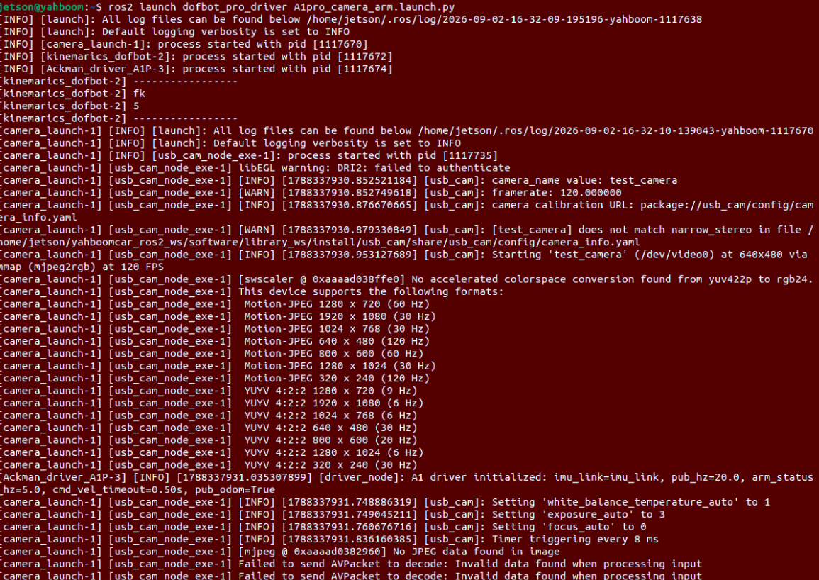
2.2 Start Robotic Arm Desktop Grasping Action Execution Node
Run in Terminal 2:
x# Depth camera version (Nuwa)ros2 run dofbot_pro_driver grasp_desktop
# Or USB camera versionros2 run dofbot_pro_usb grasp_usb2.3 Start Line Following Obstacle Clearing Master Node
Run in Terminal 3:
xxxxxxxxxx# Depth camera version (Nuwa)ros2 run dofbot_pro_driver follow_line
# Or USB camera versionros2 run dofbot_pro_usb follow_line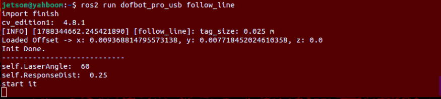
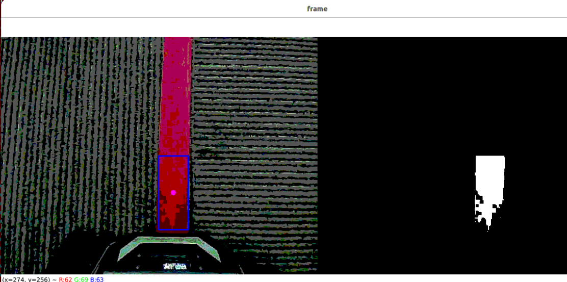
When encountering AprilTag, it performs grasping calculation for obstacle clearing:
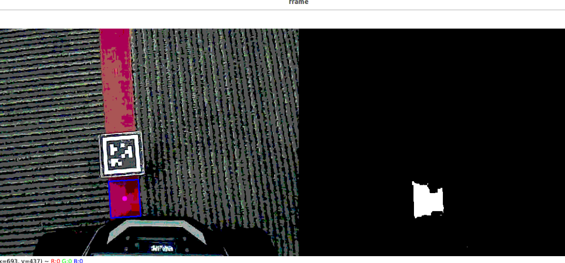
3. Operation Demo and Interaction Flow
Environment setup: Lay red guide tape track on flat ground, and place the 4×4cm AprilTag wooden block on the track line as the obstacle clearing target;
Line color selection and calibration: Place the vehicle at the track starting point, keep the image window active, press
Rkey and use mouse to box-select the ground tape to resample HSV color range;Start automatic line following: Press spacebar (
Space) on the keyboard, and the vehicle starts automatic steady driving along the guide line;Obstacle encounter secondary verification and emergency stop:
When approaching the obstacle block, the vehicle immediately stops and waits approximately 0.5 seconds;
Algorithm performs secondary stable detection to confirm the obstacle block truly exists (filtering motion blur and reflection false detections);
Robotic arm obstacle clearing and unloading:
Robotic arm automatically calculates the block's 3D spatial pose and adaptively rotates the gripper;
Descends to grasp the block, rotates to place it on the side of the track, clearing the pathway;
Automatically resume line following:
Robotic arm resets to line-following pose, vehicle automatically releases parking brake, continuing to cruise forward along the guide line.
Tip
When placing the obstacle block, try to position it approximately 20~25cm ahead of the line center to ensure the vehicle can fully see the tag features when entering the braking distance.
4. Core Source Code Analysis
The system integrates "chassis line-following control" and "vision descent grasping" dual-task closed-loop:
| Node Type | Line Following Obstacle Clearing Master Decision Node | Grasping Obstacle Clearing Execution Node |
|---|---|---|
| USB Monocular Camera | dofbot_pro_usb/follow_line.py | dofbot_pro_usb/grasp_usb.py |
| 3D Depth Camera | dofbot_pro_driver/follow_line.py | dofbot_pro_driver/grasp_desktop.py |
The main technical implementation comparison:
| Comparison Dimension | USB Monocular Solution | 3D Depth Camera Solution (Nuwa-HP60C) |
|---|---|---|
| Obstacle Distance Measurement | Pinhole imaging geometry calculates block depth | Depth map matrix directly reads tag centroid millimeter-level physical depth |
| Collision Avoidance False Trigger Prevention | Stop when detecting tag, delay 0.5s for ID secondary confirmation | Similar stop for 0.5s secondary anti-jitter mechanism (redetect_state) |
| Spatial Compensation Dimension | Superimpose X, Y 2D plane calibration deviation | Synchronously superimpose X, Y, Z 3D omnidirectional calibration compensation (offset_value.yaml) |
| Gripper Surface Mechanism | Combine tag corner vectors, adaptively rotate via compute_joint5 | Also solve compute_joint5, drive gripper parallel to the block |
4.1 Ground Guide Line HSV Recognition and Heading PID Control
Extract line centroid circle[0] through color space threshold, and calculate chassis yaw angular velocity based on its deviation from image center (320):
xxxxxxxxxx# follow_line.py —— Guide line PID cruise controlerror_x = (point_x - 320)[z_Pid, _] = self.PID_controller.update([error_x * 1.0 / 16, 0])
twist = Twist()twist.linear.x = self.lineartwist.angular.z = -z_Pid if self.img_flip else z_Pid
# Curve adaptive speed reductionif abs(error_x) > 100:    twist.linear.x = self.linear * 0.5
# Center dead zone filteringif abs(point_x - 320) < 20:    twist.angular.z = 0.0
self.pub_cmdVel.publish(twist)
4.2 Obstacle Encounter Stop and Secondary Anti-Jitter Verification Mechanism
During high-speed line-following, light shadow flickering can cause tag transient false alarms. The program designs a two-stage secondary verification after stopping:
xxxxxxxxxx# follow_line.py —— Obstacle encounter two-stage confirmation# Stage 1: First detection of tag, vehicle immediately brakes, record timestampif len(self.tags) > 0 and self.move_flag:    self.pubVel(0.0, 0.0, 0.0)    self.redetect_state = True    self.redetect_start_time = time.time()    self.redetect_tag_id = self.tags[0].tag_id
# Stage 2: After vehicle stationary for 0.5 seconds, re-verifyif self.redetect_state:    self.pubVel(0.0, 0.0, 0.0)    if (time.time() - self.redetect_start_time) >= self.redetect_wait_sec:        # Re-check if same ID tag still exists in current frame        matched_tag = next((t for t in self.tags if t.tag_id == self.redetect_tag_id), None)        if matched_tag is not None:            # Confirmed, enter grasping obstacle clearing            self.is_grasping = True            self.redetect_state = False
4.3 Spatial Depth Computation and Grasping Obstacle Clearing Closed-Loop
1. Depth Point Cloud Ranging and Gripper Adaptive
After confirming target, the depth camera version directly extracts the obstacle's true physical distance from the depth matrix, and calculates gripper deflection angle based on AprilTag edge corner vectors:
xxxxxxxxxx# follow_line.py —— Physical depth extraction and deflection angle computationc_dist = self.depth_image_info[int(center_y), int(center_x)] / 1000.0
if c_dist != 0:    vx = int(matched_tag.corners[0][0]) - int(matched_tag.corners[1][0])    vy = int(matched_tag.corners[0][1]) - int(matched_tag.corners[1][1])    self.joint5.data = int(compute_joint5(vx, vy))
    pos = AprilTagInfo()    pos.id = matched_tag.tag_id    pos.x = center_x - 10    pos.y = center_y    pos.z = c_dist
    self.pos_info_pub.publish(pos)          # Trigger grasp_desktop to execute grasping and side movement    self.TargetJoint5_pub.publish(self.joint5)
2. Obstacle Clearing Complete Auto-Resume Line Following
After the grasping node completes descent, grasping, rotation to roadside, and robotic arm reset, it publishes grasp_done topic; the line-following node releases grasping lock in the callback function, and the chassis automatically resumes forward linear velocity, achieving truly fully autonomous unmanned line-following obstacle clearing closed-loop.
4.3 Grasping Offset Tuning (Both Camera Models)
If position deviation occurs during actual grasping (such as missing, knocking over objects, offset left/right, or hitting the table), you can directly modify the spatial offset configuration file for the corresponding camera:
1. Where to Modify
Configuration files are located in the ~/yahboomcar_ros2_ws/dofbot_pro_ws/src/dofbot_pro_driver/config/ directory. Select based on camera type:
3D Depth Camera (Nuwa-HP60C):
offset_value.yamlUSB Camera:
usb_offset_value.yaml
2. How to Modify
The file contains offset parameters in X, Y, Z directions (unit: meters, recommended adjustment per tweak is 0.005~0.01, i.e., 5~10mm):
x_offset(forward/backward direction, positive toward vehicle front):Gripper extends too far and knocks over object decrease value (adjust smaller or set negative)
Gripper doesn't extend far enough and misses increase value (adjust larger)
y_offset(left/right direction, positive toward vehicle left):Gripper deviates right increase value (correct left)
Gripper deviates left decrease value (correct right)
z_offset(up/down height, positive toward ceiling):Gripper too high in air and can't grasp decrease value (probe deeper)
Gripper hits or scrapes table increase value (raise higher)